A&D TM-2657P, Instruction Manual
Discover the comprehensive Instruction Manual for the A&D TM-2657P, a highly accurate and user-friendly device. Ensure optimal performance by downloading the free manual directly from manualshive.com. This essential guide offers detailed usage instructions to enhance your experience with the TM-2657P.
Share
Download


Reviews:
No comments
Related manuals for TM-2657P

A88
Brand: DAHAO Pages: 189
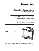
EW-BW30
Brand: Panasonic Pages: 36

RV
Brand: Garmin Pages: 6

FM-1000
Brand: CNH Pages: 132

AQ Incuba
Brand: E Instruments Pages: 2

Artist Pro 16
Brand: XP-PEN Pages: 12

CMG Series
Brand: Azbil Pages: 34

HE247
Brand: Hanns.G Pages: 23

PDK 0212-OWG13L
Brand: IEE Pages: 10

ACUBRITE 19-Nav
Brand: Acura Embedded Pages: 40

DT203/NN
Brand: Ditel Pages: 2

143300-003
Brand: Childcare Pages: 26

EFT920
Brand: Envision Pages: 14

EIZO FlexScan L 985EX L985EX L985EX
Brand: Eizo Pages: 2

DV170J
Brand: Diamond Digital Pages: 27

FlexScan L350
Brand: Eizo Pages: 2

VA2408-H
Brand: ViewSonic Pages: 44

L26W56SA and
Brand: Zenith Pages: 64


