background image


  Last Updated: October 21, 2015


OMNI-2155 


Expandable  HMI  Panel  PC 


User’s Manual 2

nd

 Ed

Summary of Contents for OMNI-2155

Page 1: ...Last Updated October 21 2015 OMNI 2155 Expandable HMI Panel PC User s Manual 2nd Ed...

Page 2: ...the original manufacturer Information provided in this manual is intended to be accurate and reliable However the original manufacturer assumes no responsibility for its use or for any infringements u...

Page 3: ...owners AMD is trademark of Advanced Micro Devices Microsoft Windows is a registered trademark of Microsoft Corp ITE is a trademark of Integrated Technology Express Inc IBM PC AT PS 2 and VGA are trad...

Page 4: ...product please make sure the following items have been shipped Item Quantity OMNI 2155 1 Phoenix power connector 1 Product CD with User s Manual in pdf and drivers 1 If any of these items are missing...

Page 5: ...n such as detailed descriptions and explanations on the product s hardware and software features if any its specifications dimensions jumper connector settings definitions and driver installation inst...

Page 6: ...transient over voltage 7 Always disconnect this device from any AC supply before cleaning 8 While cleaning use a damp cloth instead of liquid or spray detergents 9 Make sure the device is installed n...

Page 7: ...uid intrusion to the device iii Exposure to moisture iv Device is not working as expected or in a manner as described in this manual v The device is dropped or damaged vi Any obvious signs of damage d...

Page 8: ...explosion if the battery is incorrectly replaced Replace only with the same or equivalent type recommended by the manufacturer Dispose of used batteries according to the manufacturer s instructions an...

Page 9: ...Preface IX Expandable HMI Panel PC OMNI 2155 China RoHS Requirements CN AAEON Panel PC Workstation Pb Hg Cd Cr VI PBB PBDE O SJ T 11363 2006 X SJ T 11363 2006...

Page 10: ...Connections X O O O O O Chassis X O O O O O CPU RAM X O O O O O Hard Disk X O O O O O LCD X O O O O O Optical Drive X O O O O O Touchscreen X O O O O O PSU X O O O O O O The quantity of poisonous or h...

Page 11: ...1 2 8 Audio Module 9 Chapter 2 Hardware Information 10 2 1 Dimensions 11 2 2 List of Jumpers 14 2 2 1 Clear CMOS JP1 15 2 2 2 AT ATX Mode Selection JP3 15 2 2 3 LVDS Port Backlight Lightness Control M...

Page 12: ...2 3 15 DC in CN39 29 2 3 16 COM2 Connector CN40 29 2 3 17 Remote Switch Connector CN43 30 2 4 Assembling Modules 31 2 5 Installing the Hard Disk Drive 32 2 6 Installing DRAM 33 2 7 Installing the Pane...

Page 13: ...7 Configuration Optional 52 3 4 6 8 Super IO Management Serial Port 8 Configuration Optional 53 3 5 Setup submenu Chipset 54 3 5 1 Chipset North Bridge 55 3 5 1 1 North Bridge Display Control Configu...

Page 14: ...Expandable HMI Panel PC OMNI 2155 Chapter 1 Chapter 1 Product Specifications...

Page 15: ...N2807 Ethernet I0 100 1000Base TX RJ 45 x 2 Side I O USB 3 0 Type A x 1 USB 2 0 Type A x 3 SMA antenna hole x 1 HDMI x 1 CFast x 1 Bottom I O DB 9 for RS 485 422 232 x 1 10 100 1000Base T RJ 45 x 2 DB...

Page 16: ...ension W x H x D 530 x 445 x 200 mm 20 9 x 17 5 x 7 9 Gross Weight 3 kg 6 6 lb Environmental Operating Temperature 20 C 60 C with industrial grade device with 0 5 m s air flow according to IEC68 2 14...

Page 17: ...Chapter 1 Product Specifications 4 Expandable HMI Panel PC OMNI 2155 Anti Vibration 1 Grms 5 500 Hz Operation HDD Anti Shock 15 G peak acceleration 11 msec duration EMC CE FCC Class A...

Page 18: ...D Display Type 15 6 TFT LCD LED Max Resolution 1366 x 768 Max Colors 16 7M colors 6 8 bit for R G B Luminance cd m 2 5 400 nits Viewing Angle 170 H 160 V Backlight LED Backlight MTBF Hours 50 000 Touc...

Page 19: ...ar designed the OMNI 2155 can be fitted with a number of modules to expand its base capabilities Please refer to the sections below for their features 1 2 1 USB COM LAN Module Features USB 2 0 x 2 RS...

Page 20: ...1 Product Specifications 7 Expandable HMI Panel PC OMNI 2155 1 2 3 MiniCard and SIM Card Module Features MiniCard x 2 SIM Card x 2 1 2 4 RS 232 422 485 Module Features RS 232 422 485 x 4 Selectable by...

Page 21: ...PC OMNI 2155 1 2 5 Isolated RS 232 422 485 Module Features Isolated RS 232 422 485 x 4 Selectable by jumper 2k Vdc Isolation 1 2 6 Digital I O Module Features Digital I O x 8 1 2 7 CAN Bus Module Fea...

Page 22: ...Chapter 1 Product Specifications 9 Expandable HMI Panel PC OMNI 2155 1 2 8 Audio Module Features Mic in Line out...

Page 23: ...Expandable HMI Panel PC OMNI 2155 Chapter 2 Chapter 2 Hardware Information...

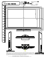
Page 24: ...Chapter 2 Hardware Information 11 Expandable HMI Panel PC OMNI 2155 2 1 Dimensions Main Panel...

Page 25: ...Chapter 2 Hardware Information 12 Expandable HMI Panel PC OMNI 2155 OMNI Modules USB CAN LAN Module Dual LAN Module MiniCard SIM Card Module RS 232 422 485 Module...

Page 26: ...Chapter 2 Hardware Information 13 Expandable HMI Panel PC OMNI 2155 Isolated RS 232 422 485 Module Digital I O Module CAN Bus Module Audio Module...

Page 27: ...le below for all of the board s jumpers that you can configure for your application Label Function JP1 Clear CMOS JP3 AT ATX mode selection JP4 LVDS Port Backlight Lightness Control Mode Selection JP5...

Page 28: ...1 Normal Default Clear CMOS 2 2 2 AT ATX Mode Selection JP3 Disable Default Enable 2 2 3 LVDS Port Backlight Lightness Control Mode Selection JP4 VR Mode PWM Mode Default 2 2 4 LVDS Inverter Voltage S...

Page 29: ...nel PC OMNI 2155 2 2 5 LVDS Inverter Voltage Selection JP6 Pin Function 1 2 12 V Default 2 3 5 V 2 2 6 Touch Selection JP8 Pin Function 1 2 4 8 wire 2 3 5 wire Default 2 2 7 COM2 12V 5V Ring Selection...

Page 30: ...CN6 Battery connector CN9 SIM socket CN10 CFast connector CN11 Board to board connector CN17 LVDS backlight connector CN18 Mini PCIe slot mSATA select CN19 SATA power connector 5V CN20 SATA connector...

Page 31: ..._REQ 8 UIM_PWR 9 GND 10 UIM_DATA 11 PCIE_REF_CLK 12 UIM_CLK 13 PCIE_REF_CLK 14 UIM_RST 15 GND 16 UIM_VPP 17 NC 18 GND 19 NC 20 W_DISABLE 21 GND 22 PCIE_RST 23 PCIE_RX 24 V3 3A 25 PCIE_RX 26 GND 27 GND...

Page 32: ...me Signal Type Signal Level 1 LAD0 I O 3 3V 2 LAD1 I O 3 3V 3 LAD2 I O 3 3V 4 LAD3 I O 3 3V 5 3 3V PWR 3 3V 6 LFRAME IN 7 LRESET OUT 3 3V 8 GND GND 9 LCLK OUT 10 LDRQ0 IN 11 LDRQ1 IN 12 SERIRQ I O 3 3...

Page 33: ...10 Pin Pin Name Signal Type Signal Level S1 GND GND S2 SATA_TX DIFF S3 SATA_TX DIFF S4 GND GND S5 SATA_RX DIFF S6 SATA_RX DIFF S7 GND GND PC1 NC PC2 GND GND PC3 NC PC4 NC PC5 NC PC6 NC PC7 GND GND PC8...

Page 34: ...PWR 5V 2 V5A PWR 5V 3 V5A PWR 5V 4 V5A PWR 5V 5 V3 3A PWR 3 3V 6 V3 3A PWR 3 3V 7 V3 3A PWR 3 3V 8 EX_PLT_RST out 9 V12S PWR 12V 10 W_DISABLE0 out 11 CLK_LPC_25M_EXT out 12 LPC_FRAME out 13 INT_SERIRQ...

Page 35: ..._REFCLKP DIFF 28 P2_RXP DIFF 29 GND GND 30 GND GND 31 P2_TXN DIFF 32 CLK_PCIE_EXIO_N DIFF 33 P2_TXP DIFF 34 CLK_PCIE_EXIO_P DIFF 35 GND GND 36 GND GND 37 PCIE_RXN3 DIFF 38 PCIE_TXN3 DIFF 39 PCIE_RXP3...

Page 36: ...IE_WAKE IN 2 3 3VSB PWR 3 3V 3 NC 4 GND GND 5 NC 6 1 5V PWR 1 5V 7 PCIE_CLK_REQ IN 8 NC PWR 9 GND GND 10 NC I O 11 PCIE_REF_CLK DIFF 12 NC IN 13 PCIE_REF_CLK DIFF 14 NC 15 GND GND 16 NC PWR 17 NC 18 G...

Page 37: ...GND GND 30 SMB_CLK I O 3 3V 31 PCIE_TX MSATA_TX DIFF 32 SMB_DATA I O 3 3V 33 PCIE_TX MSATA_TX DIFF 34 GND GND 35 GND GND 36 USB_D DIFF 37 GND GND 38 USB_D DIFF 39 3 3VSB PWR 3 3V 40 GND GND 41 3 3VSB...

Page 38: ...ctor CN19 Pin Signal 1 V5S 2 GND 2 3 9 SATA Connector CN20 Pin Pin Name Signal Type Signal Level 1 GND GND 2 SATA_TX DIFF 3 SATA_TX DIFF 4 GND GND 5 SATA_RX DIFF 6 SATA_RX DIFF 7 GND GND 2 3 10 LVDS C...

Page 39: ...18 LVDS_DDC_CLK 19 LVDSB_DATA0 20 LVDSB_DATA0 21 LVDSB_DATA1 22 LVDSB_DATA1 23 LVDSB_DATA2 24 LVDSB_DATA2 25 LVDSB_DATA3 26 LVDSB_DATA3 27 LVDSVCC 28 GND 29 LVDSB_CLK 30 LVDSB_CLK 2 3 11 HDMI Connecto...

Page 40: ...2 TMDS_CLK DIFF 13 NC 14 NC 15 DDC_CLK I O 5V 16 DDC_DATA I O 5V 17 GND GND 18 5V PWR 5V 19 HPLG_DETECT IN 2 3 12 Touchscreen Connector CN29 Pin Signal Pin Signal 1 GND 2 TOP EXCITE 3 BOTTOM EXCITE 4...

Page 41: ...dable HMI Panel PC OMNI 2155 2 3 13 LAN1 Connector CN37 Pin Signal Pin Signal 1 MDI0 2 MDI0 3 MDI1 4 MDI2 5 MDI2 6 MDI1 7 MDI3 8 MDI3 2 3 14 LAN2 Connector CN38 Pin Signal Pin Signal 1 MDI0 2 MDI0 3 M...

Page 42: ...CN39 Pin Signal Pin Signal 1 9 30V 2 GND 3 EARTH_GND 2 3 16 COM2 Connector CN40 RS 232 Pin Signal Pin Signal 1 DCD 2 RXD 3 TXD 4 DTR 5 GND 6 DSR 7 RTS 8 CTS 9 RI RS 422 Pin Signal Pin Signal 1 TXD 2 T...

Page 43: ...Chapter 2 Hardware Information 30 Expandable HMI Panel PC OMNI 2155 3 N C 4 N C 5 GND 6 N C 7 N C 8 N C 9 N C 2 3 17 Remote Switch Connector CN43 Pin Signal Pin Signal 1 EXT_PWRBTN 2 GND...

Page 44: ...nformation 31 Expandable HMI Panel PC OMNI 2155 2 4 Assembling Modules To install a module insert the connector to the OMNI slot by the side of the PCB box as shown in the image below and secure with...

Page 45: ...Installing the Hard Disk Drive 1 Place the HDD onto the bracket and secure with the screws provided 2 Hook the setup on to the bar above the PCB board as shown below Secure it with the screw provided...

Page 46: ...rmation 33 Expandable HMI Panel PC OMNI 2155 2 6 Installing DRAM To install DRAM remove the HDD and HDD bracket and insert the RAM module as shown below Users are advised to use DRAM modules provided...

Page 47: ...l as shown below with the screws provided It is advised to assemble the module before the installing the kit Note Due to the size of the isolated RS 232 422 485 RS 232 422 485 and USB COM LAN modules...

Page 48: ...Expandable HMI Panel PC OMNI 2155 Chapter 3 Chapter 3 AMI BIOS Setup...

Page 49: ...check the current system configuration against the values stored in the CMOS memory If they do not match an error message will be outputted in which case you will need to run the BIOS setup program t...

Page 50: ...when the power is turned off To enter BIOS Setup press Del or F2 immediately while your computer is powering up The function for each interface can be found below Main Date and time can be set here Pr...

Page 51: ...Chapter 3 AMI BIOS Setup 38 Expandable HMI Panel PC OMNI 2155 3 3 Setup Submenu Main...

Page 52: ...Chapter 3 AMI BIOS Setup 39 Expandable HMI Panel PC OMNI 2155 3 4 Setup Submenu Advanced...

Page 53: ...5 3 4 1 Advanced CPU Configuration Options summary Intel Virtualization Technology Disabled Enabled Optimal Default Failsafe Default Enable or Disable Intel Virtualization Technology EIST Disabled Ena...

Page 54: ...Chapter 3 AMI BIOS Setup 41 Expandable HMI Panel PC OMNI 2155 3 4 2 Advanced IDE Configuration Options summary SATA Mode IDE Mode AHCI Mode Optimal Default Failsafe Default...

Page 55: ...Configuration Options summary Legacy USB Support Enabled Optimal Default Failsafe Default Disabled Auto Enables BIOS Support for Legacy USB Support When enabled USB can be functional in legacy environ...

Page 56: ...Chapter 3 AMI BIOS Setup 43 Expandable HMI Panel PC OMNI 2155 3 4 4 Advanced Hardware Monitor...

Page 57: ...State Optimal Default Failsafe Default Power On Power Off Select power state when power is re applied after a power failure Wake on Ring Enable Optimal Default Failsafe Default Disable Enable or disab...

Page 58: ...Chapter 3 AMI BIOS Setup 45 Expandable HMI Panel PC OMNI 2155 3 4 6 Advanced Super IO Management Note Serial Port 5 8 are activated with OMNI Module...

Page 59: ...agement Serial Port 1 Configuration Options summary Use This Device Disabled Enabled Optimal Default Failsafe Default Enable or Disable Serial Port COM Possible Use Automatic Settings Optimal Default...

Page 60: ...or Disable Serial Port COM Possible Use Automatic Settings Optimal Default Failsafe Default IO 2F8 IRQ 3 IO 3F8 IRQ 4 Select an optimal setting for IO device Mode RS232 250K bps Optimal Default Fails...

Page 61: ...Enable or Disable Serial Port COM Possible Use Automatic Settings Optimal Default Failsafe Default IO 3E8 IRQ 11 IO 2E8 IRQ 11 Select an optimal setting for IO device Mode RS232 250K bps Optimal Defau...

Page 62: ...erial Port 4 Configuration Options summary Use This Device Disabled Enabled Optimal Default Failsafe Default Enable or Disable Serial Port COM Possible Use Automatic Settings Optimal Default Failsafe...

Page 63: ...summary Use This Device Disabled Enabled Optimal Default Failsafe Default Enable or Disable Serial Port COM Possible Use Automatic Settings Optimal Default Failsafe Default IO 2D0 IRQ 7 IO 2C0 IRQ 7 S...

Page 64: ...Options summary Use This Device Disabled Enabled Optimal Default Failsafe Default En Disable Serial Port COM Possible Use Automatic Settings Optimal Default Failsafe Default IO 2C0 IRQ 7 IO 2D0 IRQ 7...

Page 65: ...ptions summary Use This Device Disabled Enabled Optimal Default Failsafe Default En Disable Serial Port COM Possible Use Automatic Settings Optimal Default Failsafe Default IO 2B0 IRQ 10 IO 2B8 IRQ 10...

Page 66: ...ptions summary Use This Device Disabled Enabled Optimal Default Failsafe Default En Disable Serial Port COM Possible Use Automatic Settings Optimal Default Failsafe Default IO 2B8 IRQ 10 IO 2B0 IRQ 10...

Page 67: ...Chapter 3 AMI BIOS Setup 54 Expandable HMI Panel PC OMNI 2155 3 5 Setup submenu Chipset...

Page 68: ...Chapter 3 AMI BIOS Setup 55 Expandable HMI Panel PC OMNI 2155 3 5 1 Chipset North Bridge...

Page 69: ...55 3 5 1 1 North Bridge Display Control Configuration Options summary DVMT Pre Allocated 64M Optimal Default Failsafe Default 96M 128M 160M 192M 224M 256M 288M 320M 352M 384M 416M 448M 480M 512M DVMT...

Page 70: ...80 60Hz Optimal Default Failsafe Default 800x480 60Hz 800x600 60Hz 1024x600 60Hz 1024x768 60Hz 1280x768 60Hz 1280x1024 60Hz 1366x768 60Hz 1440x900 60Hz 1600x1200 60Hz 1920x1080 60Hz 1920x1200 60Hz 128...

Page 71: ...Chapter 3 AMI BIOS Setup 58 Expandable HMI Panel PC OMNI 2155 10 0 LVDS Backlight Control Normal Optimal Default Failsafe Default...

Page 72: ...Chapter 3 AMI BIOS Setup 59 Expandable HMI Panel PC OMNI 2155 3 5 2 Chipset South Bridge Options summary Audio Controller Disabled Optimal Default Failsafe Default Enabled...

Page 73: ...ot provide access to many of the features in the Setup utility Select the password you wish to set press Enter to open a dialog box to enter your password you can enter no more than six letters or num...

Page 74: ...ry Quiet Boot Disabled Enabled Optimal Default Failsafe Default En Disable showing boot logo Option ROM Messages Force BIOS Optimal Default Failsafe Default Keep Current Set display mode for Option RO...

Page 75: ...Chapter 3 AMI BIOS Setup 62 Expandable HMI Panel PC OMNI 2155 3 8 Boot BBS Priorities...

Page 76: ...Chapter 3 AMI BIOS Setup 63 Expandable HMI Panel PC OMNI 2155 3 9 Setup submenu Exit...

Page 77: ...Expandable HMI Panel PC OMNI 2155 Chapter 4 Chapter 4 Drivers Installation Touchscreen Settings...

Page 78: ...e Step 1 Chipset folder and select your OS 2 Open the SetupChipset exe file in the folder 3 Follow the instructions 4 Drivers will be installed automatically Step 2 Install Graphics Driver 1 Open the...

Page 79: ...al folder and select your OS 2 Open the Setup exe file in the folder 3 Follow the instructions 4 Drivers will be installed automatically Step 7 Install PenMount Touch 6000 Series Driver Resistive touc...

Page 80: ...Chapter 4 Driver Installation 67 Expandable HMI Panel PC OMNI 2155...

Page 81: ...Chapter 4 Driver Installation 68 Expandable HMI Panel PC OMNI 2155 3 Reboot and log in as administrator...

Page 82: ...Chapter 4 Driver Installation 69 Expandable HMI Panel PC OMNI 2155 4 Run patch bat as administrator...

Page 83: ...Chapter 4 Driver Installation 70 Expandable HMI Panel PC OMNI 2155 For Windows 8 1 Open the Apps Screen right click on the Command Prompt tile and select Run as Administrator...

Page 84: ...cd folder eg if the file is in a folder named abc enter cd abc 4 You are now at the folder where the file is located Enter the patch bat to open and install the drivers If your file is in a subfolder...

Page 85: ...Expandable HMI Panel PC OMNI 2155 For Windows 10 1 Open the STEP8 Serial Port Driver Optional folder and select Win10_32_64 2 Open the Setup exe file in the folder 3 Follow the instructions 4 Drivers...

Page 86: ...Panel PC OMNI 2155 4 2 PCAP Dual Monitor Touch Settings When two panels are used they can set to be the primary and secondary display The instruction below shows how this can be done 1 Go to Display...

Page 87: ...Panel PC OMNI 2155 2 Go to Tablet PC Settings in Control Panel Under Display options select the primary display from step 1 Apply the changes and exit Do NOT calibrate the screen on your own Doing so...

Page 88: ...Expandable HMI Panel PC OMNI 2155 Appendix A Appendix A Watchdog Timer Programming...

Page 89: ...cond 1 minute Watchdog Enable 0x07 Note9 0xF5 Note10 5 Note11 1 Note12 0 Disable 1 Enable Timeout Status 0x07 Note13 0xF5 Note14 6 Note15 1 1 Clear timeout status Output Mode 0x07 Note16 0xF5 Note17 4...

Page 90: ...parameter is represented from Note8 define byte EnableLDN This parameter is represented from Note9 define byte EnableReg This parameter is represented from Note10 define byte EnableBit This parameter...

Page 91: ...Expandable HMI Panel PC OMNI 2155 Appendix B Appendix B I O Information...

Page 92: ...Appendix B I O Information 79 Expandable HMI Panel PC OMNI 2155 B 1 I O Address Map...

Page 93: ...Appendix B I O Information 80 Expandable HMI Panel PC OMNI 2155...

Page 94: ...Appendix B I O Information 81 Expandable HMI Panel PC OMNI 2155 B 2 Memory Address Map...

Page 95: ...Appendix B I O Information 82 Expandable HMI Panel PC OMNI 2155 B 3 IRQ Mapping Chart...

Page 96: ...Appendix B I O Information 83 Expandable HMI Panel PC OMNI 2155...

Page 97: ...Appendix B I O Information 84 Expandable HMI Panel PC OMNI 2155...

Reviews: