background image

MaxStream

355 South 520 West, Suite 180


Lindon, UT  84042


Phone: (801) 765-9885


Fax: (801) 765-9895

[email protected]


www.MaxStream.net (live chat support)

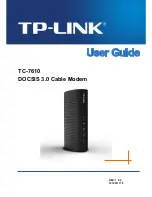
9XTend-NEMA™ RS-232/485 RF Modem

9XTend-NEMA RS-232/485 RF Modem 

Interfacing Protocol

RF Modem Operation

RF Modem Configuration

RF Communication Modes

Appendices

Product Manual 

v2.x4x

For RF Modem Part Numbers: XT09-NEMA...

1 Watt Transmit Power, 256-bit AES Encryption


M100247
2007.01.04

Summary of Contents for RS-232/485

Page 1: ...w MaxStream net live chat support 9XTend NEMA RS 232 485 RF Modem 9XTend NEMA RS 232 485 RF Modem Interfacing Protocol RF Modem Operation RF Modem Configuration RF Communication Modes Appendices Produ...

Page 2: ...in binary form include the above copyright notice this list of con ditions and disclaimer in the documentation and or other associated materials The copyright holder s name is not used to endorse pro...

Page 3: ...3 1 5 API Operation 16 3 2 Modes of Operation 17 3 2 1 Idle Mode 17 3 2 2 Transmit Mode 17 3 2 3 Receive Mode 19 3 2 4 Sleep Mode 20 3 2 5 Command Mode 22 4 RF Modem Configuration 24 4 1 Automatic DIP...

Page 4: ...True Peer to Peer no Master device required Point to Point Point to Multipoint Multidrop Retries and Acknowledgements FHSS Frequency Hopping Spread Spectrum 10 hopping channels each with over 65 000...

Page 5: ...erial Port Sleep Power Down 45 mA 45 mA Idle Currents 16 sec cyclic sleep SM 8 20 mA 19 mA 8 sec cyclic sleep SM 7 21 mA 19 mA 4 sec cyclic sleep SM 6 24 mA 20 mA 2 sec cyclic sleep SM 5 30 mA 22 mA 1...

Page 6: ...to tables in the Automatic DIP Switch Configurations section p24 regarding con figurations automatically triggered by the positions of the DIP Switches during power up RSSI LEDS RSSI LEDs indicate th...

Page 7: ...ated on the end of the CAT5 cable RS 485 422 applications will require different wir ing schemes Use the following wiring block diagram for RS 485 422 applications Figure 1 03 Wiring Block Diagram 1 3...

Page 8: ...tions on the XTend RF Modem Low asserted signals are distinguished by horizontal line over pin name DB 9 Pin RS 232 Name Pin Reference Name Description Implementation 1 DCD GPO2 Data Carrier Detect Co...

Page 9: ...ghts Reserved 9 2 1 2 Wiring Diagrams Figure 2 03 RS 232 DTE Device male DB 9 connector wired to a DCE RF modem female DB 9 Figure 2 04 DCE RF modem female DB 9 connector wired to an RS 232 DCE Device...

Page 10: ...and their implementations on the XTend RF Modem DB 9 Pin RS 485 Name Description Implementation 2 T R TRA Negative Data Line Transmit serial data to and from the RF modem 5 GND Ground Signal Ground 8...

Page 11: ...erial data sent from the RF modem 3 R RA Receive Negative Data Line Serial data received by the RF modem 5 GND Signal Ground Ground 7 R RB Receive Positive Data Line Serial data received by the RF mod...

Page 12: ...ages are available that include adapters that facilitate the following functions Performing Range Tests Testing Cables Connecting to other RS 232 DCE and DTE devices Connecting to terminal blocks or R...

Page 13: ...ter female to female Part Number JD3D3 CDN A Gray DB 9 F F The female to female NULL modem adapter is used to verify serial cabling is functioning properly To test cables insert the female to female N...

Page 14: ...munications between a host and an XTend RF Modem are dependent upon having matching baud rate parity stop bit number of data bits settings Failure to enter the modem into AT Command Mode is most commo...

Page 15: ...RF data is received the data enters the DO buffer and is sent out the serial port to a host device Once the DO Buffer reaches capacity any additional incoming RF data is lost The DO buffer stores at l...

Page 16: ...low control must be implemented in order to prevent overflow loss of data between the host and modem 3 1 5 API Operation API Application Programming Interface Operation is an alternative to the defaul...

Page 17: ...ia is met Figure 3 04 Transmit Mode Data Flow The character timeout trigger can be disabled by setting RO to zero In this case transmission will not begin until RB bytes have been received and are pen...

Page 18: ...each time a new connection sequence begins The RF initializer contains channel information that notifies receiving modems of information such as the hopping pattern used by the transmitting modem The...

Page 19: ...ed without error If the CRC data bits on the incoming packet are invalid the packet is discarded If the CRC is valid the packet proceeds to the DO Buffer Figure 3 06 Receive Mode Data Flow Refer to th...

Page 20: ...si tions to Sleep Mode and remains in its lowest power consuming state until the pin is de asserted This pin is only active if the modem is setup to operate in this mode otherwise the pin is ignored O...

Page 21: ...period of time ranging from 0 5 seconds to 16 seconds SM parameters 4 through 8 After this interval of time the modem returns to Idle Mode and listens for a valid data packet for 100 ms If the modem...

Page 22: ...ing example would change the modem s Destination Address to 0x1F To store the new value to non volatile long term memory the Write ATWR command must subsequently be sent before powering off the modem...

Page 23: ...the command will essentially be executed in the order it is received If the modem is continuously receiving data the radio will wait for a break in the received data before executing the command The C...

Page 24: ...Switches 1 2 Restore Defaults Serial Interfacing If SW1 SW2 are ON up Restore Defaults ATRE ATWR Restore Defaults Write defaults to non volatile memory If SW1 is ON up RS 232 Operation ATCS 0 RS 232...

Page 25: ...F Modem Configurations through X CTU Software Terminal Tab of the X CTU Software A terminal program has been built into the X CTU software and is located under the Terminal tab The Terminal tab provid...

Page 26: ...commands OK Exit AT Command Mode Example Utilize the X CTU Modem Configuration tab to restore default parameter values After establishing a connection between the modem and a PC refer to the Setup se...

Page 27: ...tination Address 0 0xFFFF Networking Security 2 0 E0 0x0A 10d Echo Off Command Mode Options E1 0x0B 11d Echo On Command Mode Options ER 0x0F 15d Receive Error Count 0 0xFFFF Diagnostics 2 0 FH 0x0D 13...

Page 28: ...acing 1 0 SB 0x37 55d Stop Bits 0 1 Serial Interfacing 1 0 SH 0x25 37d Serial Number High 0 0xFFFF read only Diagnostics 2 varies SL 0x26 38d Serial Number Low 0 0xFFFF read only Diagnostics 2 varies...

Page 29: ...esult of this command AP API Enable Command Serial Interfacing The AP command is used to enable the modem to operate using the frame based API operation AT Guard Time After Command Command Mode Option...

Page 30: ...axStream s X CTU Software non standard interface data rates can only be set and read using the X CTU Terminal tab Non stan dard rates are not accessible through the Modem Configuration tab When the BD...

Page 31: ...ions CF command is used to set read the command formatting setting The following commands are always entered and read in hex no matter the CF setting VR Firmware Version HV Hardware Version KY AES Enc...

Page 32: ...parame ter is useful in determining range characteristics of the RF modems under various conditions In default mode this command shows the power level in signed decimal format with the units dBm If CF...

Page 33: ...is used to set read the number of receive errors The error count records the number of packets partially received then aborted on a reception error This value returns to 0 after a reset and is not non...

Page 34: ...read the flow control threshold When FT bytes have accumulated in the DI buffer UART Receive CTS is de asserted or the XOFF soft ware flow control character is transmitted GD Receive Good Count Comman...

Page 35: ...p interval SM Command to check for a wake up initializer When a wake up initializer is detected the modem stays awake to receive data The wake up initializer must be longer than the cyclic sleep inter...

Page 36: ...ng in Cyclic Sleep Mode The Wake up Initializer Time must be longer than the cyclic sleep time that as determined by SM Sleep Mode parameter If the wake up initializer time were less than the Cyclic S...

Page 37: ...eceiving modem receives a packet with remaining forced retransmissions it calculates the length of the packet and inhibits transmission for the amount of time required for all retransmissions Thereaft...

Page 38: ...discarded PE Polling End Address Command Networking Security PE command is used to set read the modem s Polling End Address the last address polled when Polling Mode is enabled Polling Operations The...

Page 39: ...Sleep Low Power Under normal operation an RF modem in Cyclic Sleep Mode cycles from an active state to a low power state at regular inter vals until data is ready to be received If the PW parameter i...

Page 40: ...not cause default values to be stored to non volatile persistent memory For the restored default settings to persist in the modem s non volatile memory and be saved in the event of RF modem reset or...

Page 41: ...mes of silence on the UART receive lines after receiving at least 1 byte RB characters have been received by the UART RB and RO criteria only apply to the first packet of a multi packet transmission I...

Page 42: ...When the modem is pow ered the Config pin is an input During the power up sequence if RP parameter is a non zero value the Config pin is configured as an output and set low until the first RF packet...

Page 43: ...SL Command is used to set read the serial number low word of the RF modem AT Command ATRT Binary Command 0x16 22 decimal Parameter Range 0 2 Parameter Configuration 0 Disabled 1 Enable Binary Program...

Page 44: ...e current temperature of the board Sample Output 26 C when ATCF 0 1A when ATCF 1 26 when ATCF 2 AT Command ATSM Binary Command 0x01 Parameter Range 0 8 3 is reserved Parameter Configuration 0 Disabled...

Page 45: ...mmand RF Interfacing The TX command is used to set read the transmit receive behaviors of the RF modem Setting a modem to TX only TX 1 may reduce latency because the transmitting modem will never be c...

Page 46: ...ltage This is caused if the supply voltage exceeds 5 75 V Transmission is not allowed while this warning is active 3 Under temperature This is caused if the temperature sensed by the module is less th...

Page 47: ...using the AP API Enable command Use the following AP parameter values to configure the modem to operate in a particular mode AP 0 default Transparent Operation UART Serial line replacement API modes...

Page 48: ...fic structure as follows Figure 4 05 UART Data Frame API specific Structure The cmdID frame API identifier indicates which API messages will be contained in the cmdData frame Identifier specific data...

Page 49: ...acknowledgement Setting Frame ID to 0 will disable response frame Destination Address Bytes 6 7 MSB first LSB last Broadcast 0xFFFF Options Byte 8 0 Standard 1 Disable ACK RF Data Byte s 9 n Up to 204...

Page 50: ...peater Acknowledged RF Mode Acknowledged Mode Point to Multipoint Definition RF data links between one base and multiple remotes Sample Network Profile Basic Communications Base ATMY 0 set Source Addr...

Page 51: ...it determines the packet is addressed to it either as a global or local packet The receiving modem makes this determination by inspecting the destination address of the packet and comparing it to its...

Page 52: ...processes in this mode are common to all of the other RF Modes When streaming data RB and RO parameters are only observed on the first packet After transmission begins the transmission event will con...

Page 53: ...pted until the DI buffer is empty or the streaming limit TT parameter has been reached As with the first packet the payload of each follow on packet includes up to the maximum packet size PK parameter...

Page 54: ...lisions based on RSSI Buffer any incoming serial data and delay response packet transmissions until previous packet has cleared out of network For best results use the RO and RB commands to ensure tha...

Page 55: ...e probability that the repeaters will transmit at the same instant resulting in a collision and possible data loss an algorithm has been developed that will allow a variable back off prior to retransm...

Page 56: ...rough R5 which are all within range of R1 The modems R2 through R5 receive the RF packet and retransmit the packet simultaneously They also send the data out the serial ports to the PLCs Bandwidth Con...

Page 57: ...e Reliable Delivery of data Use this mode when it is critical that a base modem be able to discern data coming from multiple modems Theory of Operation A Polling Base modem will cycle through a sequen...

Page 58: ...ransmission Subsequent retransmissions incur a delay of a random number of delay slots between 0 and RN If RN is set to 0 on the TX modem there are never any back off delays between retransmissions No...

Page 59: ...he possibility of retransmissions Subsequent packets are sent without an RF initializer as the RX modems are already synchronized to the TX modem from the preceding packet s and they remain synchroniz...

Page 60: ...tions that require Reliable Delivery of data Use this mode when it is critical that a base modem be able to discern data coming from multiple modems Theory of Operation A Polling Base modem will cycle...

Page 61: ...sting This equipment has been tested and found to comply with the limits for a Class B digital device pursuant to Part 15 of the FCC Rules These limits are designed to provide reasonable protection ag...

Page 62: ...device has been tested with Reverse Polarity SMA connectors with the antennas listed in the tables of this section When integrated into OEM products fixed antennas require installation preventing end...

Page 63: ...ment Yagi RPTNC 8 1 dBi 2 1 dB Fixed Mobile Table A 03 Omni directional base station antennas approved when operating at 1 watt power output or lower Part Number Type Connector Gain Required Antenna C...

Page 64: ...ic mount w 12ft pigtail RPN 3 0 dBi Fixed A09 D3SM P12F omni directional w 12ft pigtail RPSMA 3 0 dBi Fixed A09 D3PNF omni directional permanent mount RPN 3 0 dBi Fixed A09 D3TM P12F omni directional...

Page 65: ...ower output or lower Part Number Type Connector Gain Application A09 Y6 2 Element Yagi RPN 6 1 dBi Fixed Mobile A09 Y7 3 Element Yagi RPN 7 1 dBi Fixed Mobile A09 Y8 4 Element Yagi RPN 8 1 dBi Fixed M...

Page 66: ...A PARTICULAR PURPOSE IN NO EVENT SHALL MAXSTREAM ITS SUPPLIERS OR LICENSORS BE LIABLE FOR DAMAGES IN EXCESS OF THE PURCHASE PRICE OF THE PRODUCT FOR ANY LOSS OF USE LOSS OF TIME INCONVENIENCE COMMERC...

Reviews: