background image

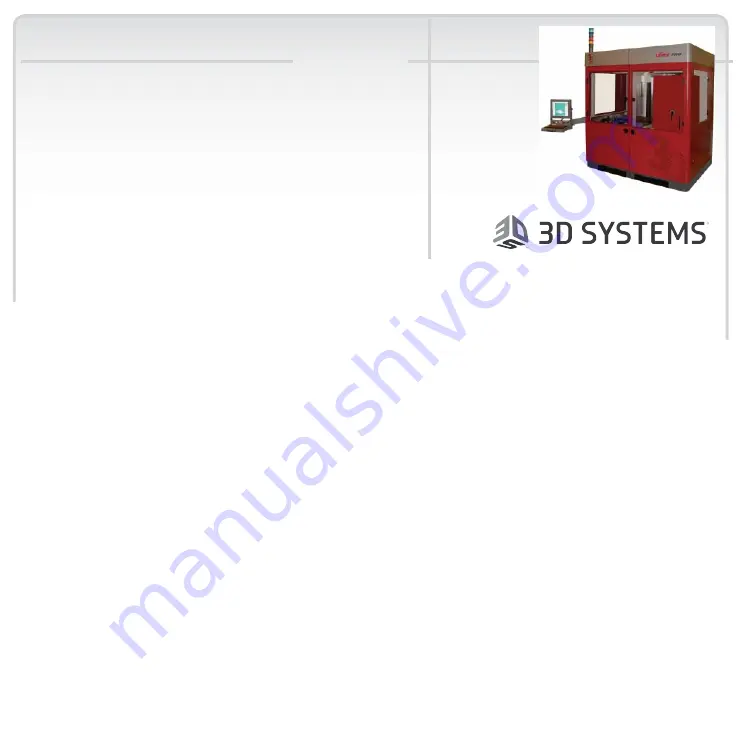
Viper Pro 

q u i c k   s t a r t
g u i d e

Thank you for purchasing the Viper Pro


system .


Before using this equipm ent,

 please read this guide 

carefully 

to 

enjoy 

optim um  

perform ance 

and 

longer 

service life.

Docum ent 23XXX-M XX-00

Revision 1X DRAFT

Decem ber 2005

Copyright © 2005 by 

3D System s Corporation.

 All rights 

reserved.

3D System s,

 the 

3D System s logo, and Viper Pro 

are 

registered 

tradem arks of 3D System s,Inc.

O ther tradem arks 

are the property 

of their respective ow ners.

To prepare and build a part, see Quick System Overview on page 11.

The Viper Pro system runs on 200-240 VAC / 50-60Hz, single phase power 30A for the single 
resin delivery module and 50A for the dual and extra large resin delivery module.
i

See “Facility Requirements Guide: Viper Pro SLA System” for complete Viper Pro system electrical, 
mechanical, environmental, and network requirements.

What’s Inside? 3
New Features  7
Hazard Messages 9
Other Useful Documents 10
Quick System Overview 11
Operator Interface 15
RDM Installation and Removal 16
RDM Removal 34
Software Overview 40

Gel and Debris Filtering 46
Recoater Module 48

Image Projection Module 49

Lasers 51
Safety 54
Maintenance 60
Glossary 62
Troubleshooting 75

Summary of Contents for Viper Pro SLA iPro 8000

Page 1: ...t i veowner s To prepare and build a part see Quick System Overview on page 11 The Viper Pro system runs on 200 240 VAC 50 60Hz single phase power 30A for the single resin delivery module and 50A for the dual and extra large resin delivery module i See Facility Requirements Guide Viper Pro SLA System for complete Viper Pro system electrical mechanical environmental and network requirements What s ...

Page 2: ...q u i c k s t a r t g u i d e 2 Customer Support 78 Legal Notices 79 ...

Page 3: ... Container Recoater and Scanning System these features are improvements over the other SLA models Hazard Messages This section describes the safety messages included in this manual Other Useful Documents Here you ll find a listing of other documents that may be helpful to you as you use the Viper Pro Quick System Overview This section gives you a quick look at everything on the Viper Pro Operator ...

Page 4: ...that is connected to the Viper Pro It includes the pictures of software screens as well as information on how to open start complete and remove a build Debris Filtering This section tells you how to filter debris from the Viper Pro Image Projection Module This section gives information on geometric calibrations and laser calibrations xx et al Safety Read this section before you start a Viper Pro b...

Page 5: ...and low Viper Pro down time You can perform some maintenance procedures Semi annual preventive maintenance requires a certified 3D Systems Customer Support Representative xx Brian Ward to give important information Glossary Are you wondering what stereolithography is all about Do you have questions about the SmartSweep Recoating Process In this section we ve covered the definitions that you need t...

Page 6: ...e w h a t s i n s i d e 6 Customer Support Have you read everything and you still can t figure it out Give us a call This section tells you how We re glad to help Legal Notices This section explains our legal stance please read it ...

Page 7: ...le can upgrade to a dual resin delivery module in less than two days Dual Resin Delivery Module The Viper Pro can also build parts in two separate build zones Each zone is independently capable of supporting its own active resin delivery module and motion axis control allowing controlled builds in both zones simultaneously and allowing those builds to use different resins Extra Large Resin Deliver...

Page 8: ...an ten minutes you can also swap the resin delivery module easily without coming into contact with resin All components that come in contact with resin in the resin delivery module are removed with the module itself You can remove the resin delivery module easily and quickly and replace it with another active resin delivery module without having to clean any wet resin surface This new feature sign...

Page 9: ...iper Pro Damage Hazard Machine damage part damage and or data loss can result if you ignore this type of hazard message Electric Shock Hazard Injury or death from electric shock can result if you ignore this type of hazard message UV Radiation Hazard Eye injury or blindness can result if you ignore this type of hazard message Irritant Hazard Bodily irritation or allergic reaction can result if you...

Page 10: ...uide This multi language document has everything that you need to know in order to handle and dispose of Viper Pro material safely It also includes relevant regulatory guidelines for material disposal worldwide Viper Pro Facility Requirements Guide To see what preparation you must do for your site prior to installing the Viper Pro read Facility Requirements Guide Viper Pro SLA System A pdf copy is...

Page 11: ...q u i c k s t a r t g u i d e q u i c k s y s t e m o v e r v i e w 11 Quick System Overview picture with callouts here ...

Page 12: ...q u i c k s t a r t g u i d e q u i c k s y s t e m o v e r v i e w 12 ...

Page 13: ...q u i c k s t a r t g u i d e q u i c k s y s t e m o v e r v i e w 13 ...

Page 14: ...q u i c k s t a r t g u i d e q u i c k s y s t e m o v e r v i e w 14 ...

Page 15: ...e is a control panel with a separate emergency stop for safety The e stop is tied to safety circuitry and removes power from the motion system heaters laser and other things when pressed The chamber light switch is a lighted switch that turns the chamber light on and off when pressed by stating CHAMBER LIGHT The laser on indicator light shows when the laser contractor is on and then the laser may ...

Page 16: ... is very heavy and may require more than one person to remove or install it While wearing protective clothing disposable nitrile gloves and goggles follow these steps 1 Open the RDM door roll the RDM to the side of the machine in which you want to place it 2 Make sure that the connecting cables are out of the way of the RDM before you attempt to place the RDM in the machine 3 Make sure that the el...

Page 17: ...machine connect the cables There are two black power cords the heater and the RDM I O connector Plug the three pronged power cord into the outlet and place the connector into the top of the keys See Figure 2 Open I O Connector on page 18 and Figure 3 I O Connector with Cable on page 18 When properly placed the connector lines up with the keys You cannot install the I O connector incorrectly ...

Page 18: ...t g u i d e r d m i n s t a l l a t i o n a n d r e m o v a l 18 Figure 2 Open I O Connector Figure 3 I O Connector with Cable 7 Make sure that the white switch is in the ON position See Figure 4 White Switch on page 19 ...

Page 19: ...q u i c k s t a r t g u i d e r d m i n s t a l l a t i o n a n d r e m o v a l 19 Figure 4 White Switch 8 Close the Viper Pro door ...

Page 20: ...tact are in place the user does not need to worry about such contact The RDM allows the user via a screen to strain the debris that inevitably accumulates in the machine so that it can be removed in a similar manner to the removal of build platforms It also removes the higher viscosity resin that settles on the bottom of the delivery module circulates the resin to help prevent gel formation and st...

Page 21: ...y accidental dispensing of the full 10kg resin container without allowing overspilled resin It can also capture resin surface debris An empty resin container can be used for overflow storage The manual valve of 2 in pipe is the same shape as the bottom of the surface which makes the resin delivery module fully drainable Therefore there are no trapped volumes of liquid Table 1 Build Envelope Maximu...

Page 22: ...e RDM can be heated either outside the Viper Pro s enclosure via the stand by mode or in the enclosure Resin can be heated from a room temperature of 200 C to 260 C up to a maximum temperature of 450 C via accelerated heating and 340 C via gradual heating Auto Resin Refill System The auto resin refill system is behind the auto resin refill door This system adds resin to the RDM from a resin contai...

Page 23: ...fore proceeding with these steps While wearing protective clothing disposable nitrile gloves and goggles perform the following steps 1 Open the front machine door that corresponds to the resin s build zone until the vent hold on the topmost end of the bottle is visible 2 Place the vent cap on the vent hole and screw tightly to prevent the resin from spilling 3 Pull the RDM release lever located to...

Page 24: ...4 Figure 5 Release Lever 4 When the resin has properly drained release the inner latch and lift until the resin container is visible 5 Push the container release button See Figure 6 Container Release Button on page 25 located on the lower right corner of the resin bin Release Lever ...

Page 25: ...carefully lift it from the container slot place the vent cap back on dispose of the container according to local regulations Partially Empty Resin Container Removal When the resin container is empty and needs additional resin perform the following procedure It is important to verify the type of resin currently in the RDM before proceeding with these steps While wearing protective clothing disposab...

Page 26: ...e resin bin Figure 5 Release Lever on page 24 toward you 4 When the resin has properly drained release the inner latch and lift until the resin container is visible 5 Push the container release button Figure 6 Container Release Button on page 25 located on the lower right corner of the resin bin 6 Lift out the resin container 7 Using a disposable paper towel wipe all resin from the container seal ...

Page 27: ...q u i c k s t a r t g u i d e r d m i n s t a l l a t i o n a n d r e m o v a l 27 Figure 7 Container Lifted ...

Page 28: ... Before starting this procedure make sure that the container slot is empty If a container is present refer to the previous section Removing Empty Resin Containers before continuing While wearing protective clothing disposable nitrile gloves and goggles perform the following steps 1 Open the resin refill door until it is completely inverted ...

Page 29: ...rly closed 6 Remove the vent cap and place it on the cap retainer for storage 7 Using the puncture tool place a small vent hole in the center of the vent spout 8 When the vent hole has been made return the puncture tool to the holding clips 9 Close the resin container door firmly until it latches securely Leveling Bottle A leveling bottle contained in the right receptacle is connected to the level...

Page 30: ... t i o n a n d r e m o v a l 30 Figure 9 Refill Bottle Refill Bottle The refill bottles contained in the middle and left receptacle are connected to the refill pump Each bottle moves resin from the refill container See Figure 9 Refill Bottle on page 30 ...

Page 31: ...lace a resin container into the container slot and remove the container lid and the induction seal 4 Close the container holder cover until the inner cover latch has been properly locked 5 Lift the resin refill door until the vent cap faces up and the refill door is nearly closed 6 Remove the vent cap and place it on the cap retainer for storage 7 Using the puncture tool place a small vent hole in...

Page 32: ...he RDM To maintain the resin level properly in relation to the laser and platform an electronic assembly controls the RDM lifters These lifters move the module up or down according to the fluctuation of the resin level within the RDM If the electronic assembly does not raise the RDM to meet the optimum resin level the 3D Print Software notifies the user to add resin or to remove resin To add resin...

Page 33: ...n 3 Using the same type of resin that is currently in the RDM slowly pour the resin in the corner of the module Caution Be careful with resin Pour resin into the corner nearest the Z stage or rear of the RDM to help the system to recognize quickly whether the overall resin temperature needs to be adjusted To reduce bubbles pour the resin slowly 4 When the message Stop adding resin Press any key to...

Page 34: ...4 RDM Removal The RDM is made of stainless stell and has casters for moving and maneuvering it while installing or removing it from the frame There are also handles on the RDM that help the user to transport and maneuver it into and out of the Viper Pro ...

Page 35: ... c k s t a r t g u i d e r d m r e m o v a l 35 RDM Temperature possible software explanation to be added Figure 10 RDM Temperature To set the RDM temperature contact a qualified 3D Field Service Technician ...

Page 36: ...11 Manual Move Operations Screen Platform Installation possible software included in this stage picture included The RDM must be in the machine before this process starts When correctly installed the platform sits on the elevator platform mount 1 Make sure that the elevator motion stage is at its highest setting ...

Page 37: ...evator main stage moves to the Build Start position Platform Release After the build is complete select drain platform This function raises the elevator motion stage to the top and the locking mechanism disengages The user can then reach in move the platform backward release the locking tab and then slide the platform back and remove it Is the RDM Full Recoating with the Vacuum On Levelling the re...

Page 38: ...uild Blade Installation Do we need pictures See pp 34 36 of hardware manual Recoating Process The recoating process combines elevator and recoater blade movements to apply liquid resin to the top of the part so that the next layer can be built Recoater Blades The recoater blade is on a rail system above the resin delivery module ...

Page 39: ... window on one face of the blade allows the user to view the level of resin inside the reservoir The blade is attached at both ends to precision anti friction linear guides which attach to the rim Two belts drive the Zephyr recoating system A vacuum system attaches to the recoater blade to maintain the level of resin within the blade 3D Systems Customer Support Engineers will adjust the blade for ...

Page 40: ...q u i c k s t a r t g u i d e s o f t w a r e o v e r v i e w 40 Software Overview Main Page Figure 12 Main Screen of the 3DPrint Software ...

Page 41: ... a r t g u i d e s o f t w a r e o v e r v i e w 41 Build Open Is this the same as loading a part To load a part follow these steps Open a BFF file Look at the machine screen Figure 13 Machine Setting Select options ...

Page 42: ...q u i c k s t a r t g u i d e s o f t w a r e o v e r v i e w 42 Figure 14 Machine Scale Settings Put appropriate ED and DP ...

Page 43: ...q u i c k s t a r t g u i d e s o f t w a r e o v e r v i e w 43 Figure 15 Machine Options Setting Select options ...

Page 44: ...q u i c k s t a r t g u i d e s o f t w a r e o v e r v i e w 44 Figure 16 Machine Build Offsets Setting How to get these in Hmmmm PLAY STOP PAUSE Figure 17 The Screen That Allows You to Open a Build ...

Page 45: ...f t w a r e o v e r v i e w 45 Build Start Figure 18 The Screen That Allows You to Start a Build Build Complete Figure 19 The Screen That Allows You to Complete a Build Build Remove Figure 20 The Screen That Allows You to Remove a Build ...

Page 46: ...is that has settled to the bottom of the RDM Gel may agglomerate into larger masses may gradually increase in molecular weight because of chain growth and may or may not settle to the bottom of the RDM depending on the specific resin and the state of the gel Debris removal avoids some gel formation although not all gel is related to larger debris Gel can be very difficult to actually remove as it ...

Page 47: ... system as needed to build on the SLA system Platform and Platform Supports The platform supports hold the platform while it moves up and down during part building The platform is made of perforated stainless steel and has special locking slots to secure it to the platform supports NOTE Verify that the platform has been thoroughly cleaned and dried before placing the platform into the platform sup...

Page 48: ...nd dried before placing the platform into the platform support frame The platform support for the Viper Pro is a frame with two sliding clips on the front and two locating points on the back Install the platform onto the platform support assembly by making sure that the back side of the platform engages the locating points on the platform support Once the platform has been installed properly slide...

Page 49: ...ate All optics components are mounted to a single optics plate or substrate The IPM must be aligned before installing it onto the Viper Pro Geometric Calibration on the Plane For geometric calibration on the plane please contact a 3D Systems Field Service Engineer Laser Power Calibration Laser power calibration requires a 3D Systems Field Service Engineer Laser Power Reading In the Build Screen a ...

Page 50: ...q u i c k s t a r t g u i d e i m a g e p r o j e c t i o n m o d u l e 50 Beam Rest Position The beam hits a piece of plastic and glows ...

Page 51: ...tant power during operation at a maximum of 1000W at the resin delivery module Optical Output The IPM has two separately controlled image projection systems or scanners that can be selected by use of a two position mirror mechanism that directs the beam to and from the laser head to the selected scanner The minimum power output of the IPM is 1W with a maximum input of 2W The image projection surfa...

Page 52: ...o 5 of the commanded value It also provides ellipticity between xx what are the units here 0 9 and 1 1 on each image plane Sensors that can detect and measure beam properties or profilers are on the process frame These sensors monitor beam diameter ellipticity and power and actively calibrate each scanner s pointing in order to compensate for position drift The pointing drift monitoring capability...

Page 53: ...lly interfaces to the laser head heat sources All liquid lines use dry dry quick disconnect couplings A 3D Systems Customer Support Engineer should perform any other servicing of the chiller or heat exchanger Beam Profilers The SLA system contains two beam profilers that are located near the front and rear of the resin delivery module The profilers determine the actual X and Y axis location of the...

Page 54: ... normal operation the laser beam is completely confined and the viewing windows in the Process Module block UV radiation Control Switches The locations of control switches are described in the chapter SLA System Hardware Master and Emergency power shut off switches are located as described in the following sections Master Power Shut off The Viper Pro has a master circuit breaker switch located on ...

Page 55: ...he Control Panel section in the chapter SLA System Hardware ID Certification Labels A label on the Viper Pro certifies laser safety conformance to the Code of Federal Regulations CFR This label also gives power and ID information This label is on the front door in the upper right corner of the Viper Pro Safety Warning Labels On the Viper SLA system labels are affixed on the frame behind the vat do...

Page 56: ...lly cured parts Epoxy resin is less viscous and splashes more easily than acrylate resin Wearing contact lenses when working with resins is not recommended Always wear chemical resistant gloves whenever handling resins or partially cured parts Recommended gloves are 100 Nitrile Do NOT wear latex gloves Always work in a well ventilated area when using resins Avoid breathing vapors Always wash skin ...

Page 57: ...topics consult the 3D Systems Resin Handling and Safety Guide Resin Storage Resin should be stored in opaque non reactive containers according to the guidelines given in the MSDS included with the resin Protect resin from sunlight and ambient room light Resin may be stored in vats with the lid securely fastened Pouring resin back into the original containers is acceptable but be sure to leave seve...

Page 58: ...so they are available to contain the affected area in the event of a major resin spill The spilled resin should then be absorbed on inert absorbent material and placed into drums for transfer to an approved waste disposal site After cleaning up the spill individuals should wash thoroughly with soap and cold water All clothing should be washed before reuse Avoid exposure to sunlight until skin and ...

Page 59: ...large amounts of water for 15 minutes avoid sunlight fluorescent light and other ultraviolet light and obtain immediate medical attention Eye wash facilities and a first aid kit should be readily available and close to the resin Contact Lenses If resin splashes into the eye when contact lenses are worn flush the eye with water immediately Verify that flushing has removed the contact lens from the ...

Page 60: ...llowing these guidelines Remove dust from the outer surfaces of the Viper Pro by wiping with a clean dry lint free cloth Caution dust and clean the outside surfaces only Do not dust inside the build chamber or feed slots Remove dirt and grease from the Viper Pro by spraying all purpose cleaner on a clean cloth and gently wiping Caution use only non abrasive alcohol free cleaners to clean surfaces ...

Page 61: ...ly wipe the buttons and windows Caution Remove the build platform before cleaning the operator control panel buttons doing so will prevent the machine from initiating any actions when buttons are pressed Scheduling Preventive Maintenance Your Viper Pro must have preventive maintenance PM performed by a qualified 3D Systems Customer Support Representative Contact 3D Systems after either one year of...

Page 62: ...bution automatically calculates drawing speeds to determine whether the laser should be adjusted or replaced and to indicate whether the optics should be adjusted replaced or cleaned Beam profiler A UV sensitive detector over which the laser beam is moved to generate beam profiles Two beam profilers are mounted in the process chamber in opposing corners of the rim Border A vector that defines the ...

Page 63: ...an SLA system Build style A template file that defines slicing and part building parameters Bullet The characteristic shape of the solid plastic created by a stationary laser beam on the surface of photocurable resin CAD Computer Aided Design The process of designing products by interaction with a computer rather than by the traditional method of hand drawing on paper CAD resolution The internal a...

Page 64: ...cturing operations with the assistance of computers CDRH Center for Devices and Radiological Health CFR Code of Federal Regulations Chamber temperature The controlled temperature in the process chamber Control module One of the two modules that comprise the SLA 3500 and Viper SLA systems Control computer The computer mounted in the SLA system cabinet that controls the building of stereolithographi...

Page 65: ...er and distribution laser draw speed and resin characteristics Curl A characteristic type of part deformation Draining Allowing resin to drip from the finished part into the vat when the elevator is at its top position Drawing speed The speed at which the laser traces over the surface of the resin to form solid plastic lines and surfaces The laser drawing speed varies depending on the depth of sol...

Page 66: ...led Z stage Exposure The total light energy absorbed by a point on the resin surface Exposure increases with higher laser power and decreases with higher drawing speed Fill vectors skin fill Overlapping parallel vectors that comprise the horizontal surfaces skins of stereolithographic parts Green part A stereolithographic part prior to UV post curing but after laser curing in the resin delivery mo...

Page 67: ...ight energy required to polymerize photocurable resin Layer Thin horizontal section of laser solidified resin Layer thickness The depth of a solidified layer of resin as requested by the user Leveling The process whereby the surface of the resin is adjusted to the correct distance from the dynamic mirrors Line A line of cured plastic generated by overlapping bullets See also vector Linewidth The h...

Page 68: ...tion of toxic substances and safe handling guidelines NIOSH National Institute for Occupational Safety and Health Photoinitiator A chemical in photopolymers that reacts with photons and catalyzes the polymerization process Photopolymer A chemical substance composed of photoinitiators and monomers that polymerizes when exposed to light energy Photopolymerization The process whereby light energy con...

Page 69: ... the polymer helps to determine the mechanical properties of the plastic material Polymerization The process of linking small molecules monomers into larger molecules polymers comprised of many monomer units Post Curing Apparatus PCA equipment A device which generates ultraviolet energy used to cure green stereolithographic parts Post process The process of cleaning curing and finishing stereolith...

Page 70: ...ng a layer of liquid resin with a user specified thickness on top of the previously cured layer Recoat style A style file that defines parameters associated with recoating during the stereolithographic process Recoater assembly The assembly of an SLA system that either applies resin to or removes excess resin from the part as the recoater blade moves across the vat Recoater blade The part of the r...

Page 71: ...vice that blocks the laser beam when an interlock switch is activated or when closed via the computer user interface Scan speed See Draw speed Sensitization An allergic response to a chemical stimulus such as resin generally resulting from repeated skin contact Skin skin fill See Fill vectors SLA system See Stereolithography apparatus Stereolithography apparatus The equipment used to produce stere...

Page 72: ...s by solidifying successive layers of photocurable resin Stereolithography file STL The tessellated triangulated CAD input file Supports Structures designed on the CAD system or by 3D Lightyear File Preparation Software to support a part above the elevator platform provide a rigid foundation on which the object may be built and attach and support layer sections Sweep A pass of the recoater blade f...

Page 73: ...om the mass of the part Triangle normals are used to differentiate between inside and outside surfaces of a solid Ultraviolet UV Electromagnetic radiation having a wavelength shorter than visible light i e below 390 nanometers Vector A directed line segment represented by starting and ending coordinates as defined in a stereolithography slice or build file Workstation The high powered personal com...

Page 74: ...t improving trapped volume sweeping Z Stage See Elevator 3D Lightyear File Preparation Software Software used to verify STL files orient parts select build style parameters generate supports and create the files that are used for building on the SLA system 3dverify software A function in 3D Lightyear File Preparation Software that verifies and fixes STL files ...

Page 75: ... power is restored preventing damage from power flickers and surges 2 When the power is restored and stable switch the Viper Pro power ON at the file cabinet Viper Pro Shutdown If you do not plan on operating the Viper Pro on a regular basis and want to shut it down for an extended period of time shut down Windows and turn off the main disconnect Note It takes a substantial amount of time for the ...

Page 76: ...ugh the RDM s on board delivery system The resin warranty is void if material is added manually to the RDM STOP INCORRECT MATERIAL ERROR Resin Container Installed is Wrong Type This RDM contains You are attempting to install This material cannot be added into the RDM through the RDM s on board delivery system The resin warranty is void if the material is added manually to the RDM EMPTY CONTAINER E...

Page 77: ...rd delivery system The resin warranty is void if the material is manually added to the RDM MATERIAL QUANTITY ERROR Quantity of Material and Recorded Quantity Do Not Match The quantity of material in this container does not match its last recorded quantity This material cannot be added into the RDM through the RDM s on board delivery system The resin warranty is void if the material is added manual...

Page 78: ... number of the Viper Pro located on the rear panel A brief description of the problem including the exact error message When the problem occurred for example when you submitted a job during the begin ning or the end of a build or after power off recovery Customer Support Hotline Please contact your Customer Support Hotline at one of the following numbers In North America call 1 800 793 3669 In Asi...

Page 79: ... the responsibility of the Licensed User to provide 3D Systems with current information as to its name and address The Licensed User also undertakes to notify 3D Systems promptly in the event that it considers any of the data contained in this document to be incomplete or erroneous in any respect in connection with Licensed User s particular use or generally FCC Notice This equipment has been test...

Page 80: ...i d e 1 B build zone 7 build start 20 D Dual Resin Delivery Module 7 E Extra Large Resin Delivery Module 7 F Features 7 K keyboard 15 M mode stand by 21 22 O overflow compartment 21 overflow storage 21 R resin level control 21 ...

Page 81: ...q u i c k s t a r t g u i d e 2 resin surface debris 21 resin changing 20 S Single Resin Delivery Module 7 Z Zephyr recoater blade 20 ...

Reviews: