background image


TD_UserManual_SCALEREO-Desk_13xyyC  

Rev. 1.4 / 25.02.2022 


1

 / 29 

3D Global Solutions GmbH 

Am Krebsgraben 15 / Geb. 2.2 

DE-78048 Villingen-Schwenningen


www.3dgs.eu / [email protected] 

Tel.: +49 (0) 7721-916 19 60 
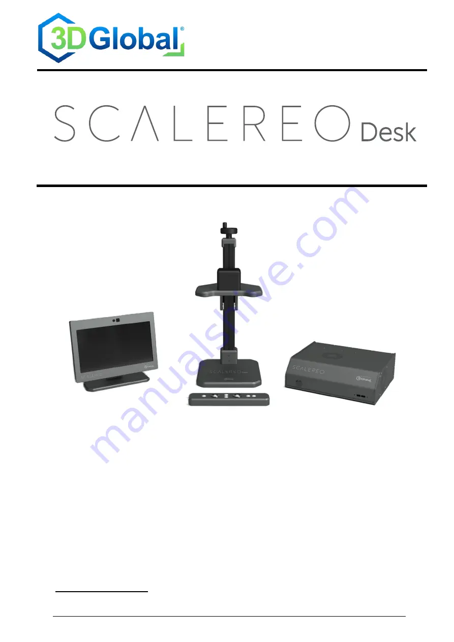
 

User Manual 


Stereo 3D Video Microscope System 


Article designations 

SCALEREO-Desk_13xyyC 

whereby x is a placeholder for A-Z and y a placeholder for 0-9 as possible product variants 

Summary of Contents for SCALEREO Desk

Page 1: ...Am Krebsgraben 15 Geb 2 2 DE 78048 Villingen Schwenningen www 3dgs eu info 3dgs eu Tel 49 0 7721 916 19 60 User Manual Stereo 3D Video Microscope System Article designations SCALEREO Desk_13xyyC whereby x is a placeholder for A Z and y a placeholder for 0 9 as possible product variants ...

Page 2: ... whole or in part only with the express written permission of 3D Global Solutions GmbH 3D Global and the 3D Global Logo are registered trademarks of 3D Global GmbH SCALEREO is a registered trademark of 3D Global Solutions GmbH All other trademarks names and logos are trademarks or registered trademarks of their respective owners ...

Page 3: ...s accessories required 11 2 5 Symbols used 12 2 6 General safety instructions 12 2 7 Warning Lighting 13 2 8 Perception of stereoscopic images 13 2 9 Epilepsy warning 13 3 Commissioning 14 3 1 General instructions 14 3 2 Unpacking installing 14 3 2 1 Unpacking box 1 14 3 2 2 Unpacking box 2 15 3 3 Commissioning 16 3 3 1 Cables and connections 16 3 3 2 System start 17 4 Operation 18 4 1 Positioning...

Page 4: ... 24 4 8 1 Camera 24 4 8 2 Foot switch 25 4 8 3 Headtracking 25 4 8 4 Data 25 4 8 5 Logging 25 4 8 6 Advanced 26 4 8 7 Information 26 5 Problem remedies FAQ 27 6 Technical data 27 7 Annex 28 7 1 Notes on the CE mark 28 7 2 Notes on cleaning the system 28 7 3 Decommissioning disposal instructions 28 7 4 Support 29 ...

Page 5: ...elevant technical data on the system and is to be regarded as an integral part of this user manual This user manual forms an integral part of the device and must therefore always be kept available for reference and passed on if the device is sold The type plate of the device contains various symbols whose meaning is described here Before using the device for the first time read this user manual co...

Page 6: ...th ready installed adjustable display stand and cables for power supply image signal and tracking camera signal per manently attached to the display 1x this user manual incl separate datasheet document Box 2 contains 1x Desk microscope unit with permanently attached cables for power supply illumination camera control and camera signal 1 Signal Processing Unit SPU Central control signal processing ...

Page 7: ...d to continuously adjust the 3D image on the display so that the user can move relatively freely in front of the display The user just has to maintain a viewing distance of approx 55 80 cm to the display within a predefined viewing area approx 22 5 to the centre axis of the display This allows the user to maintain an upright and thus healthy posture at all time when using the system Due to the hea...

Page 8: ...ively for the following types of use 2 1 2 1 User groups Users of legal age within the scope of their professional commercial activity Only one person at a time not multiple users simultaneously Only persons with binocular two eyed defect free vision For persons with impaired vision on at least one side spatial perception may only be possible to a limited extent or not at all See also paragraph 2 ...

Page 9: ...e following demands on the user 2 2 2 1 Viewing area area in front of the display in which the user s eyes must be located Distance viewing distance VD orthogonally to the centre of the display approx 55 80 cm ideal 65 cm Width horizontal viewing angle VA orthogonally to the centre of the display approx 70 cm at the ideal distance 22 5 Height vertical viewing angle VA orthogonally to the centre of...

Page 10: ...emblies interconnected by cables For unsecured placement on a stable flat surface of a suitable table with sufficient load bearing ca pacity and an ergonomically expedient height e g inspection workstation 2 2 3 4 System Electrical power supply Cold appliance socket C13 230 VAC 50 60 Hz 16 A power supply 2 2 3 5 System IT USB port Type A Transfer of locally stored image content to USB stick All ot...

Page 11: ...asily inflammable materials On a stable flat surface of a suitable table with sufficient load bearing capacity and an ergonomically expedient working height e g inspection workstation No direct sunlight Temperature range 10 40 C Relative humidity max 80 at temperatures up to 30 C then linear decrease to 50 at 40 C Altitude max 2000 m above sea level Atmospheric pressure min 800 hPa Mains voltage f...

Page 12: ...se the device to rain or moisture otherwise short circuits or electric shocks may occur Lay connecting cables in such a way that they do not pose a danger The mains cable must not be kinked or otherwise mechanically strained Disconnect the device completely from the mains if it is not to be used for a longer period of time We recommend unplugging the mains cable to completely disconnect the device...

Page 13: ...y experience undesirable effects such as dizziness eye ache headache fatigue or nausea when viewing stereoscopic images especially when viewing content with very strong 3D effects Persons with impaired eyesight or de fective vision may also experience such or similar effects to a more frequently or intensified extent Relieve the strain on your eyes by taking regular breaks from use to focus on a d...

Page 14: ...ng please refer to paragraph 7 2 on page 28 Relax your eyes at regular intervals by focusing on a distant real object for some time Blink more frequently Regular breaks are recommended when using the device 3 2 Unpacking installing To avoid damage to the system the individual devices must be unpacked and in stalled and the cables connected as described here Please adhere closely to the sequence gi...

Page 15: ...t down the desk microscope unit at its intended installation location Remove the microscope slide plate yellow arrow and place it with the desired side white or black facing upwards into the recess provided in the base plate of the tabletop microscope unit Move the camera illumination head of the tabletop microscope unit to the lowest possible position scale arrow points to 0 using the turning dev...

Page 16: ...onnect the headtracking signal cable USB A of the display tracking unit to any USB port on the rear of the SPU Connect the power supply cable of the display tracking unit to the designated Power Display socket on the rear of the SPU Connect the USB B plug of the ControlBar signal cable to the designated USB port on the right hand side of the ControlBar Connect the USB A plug of the ControlBar sign...

Page 17: ...lizes the area under the microscope on the 3D display Note that the complete system start can take up to 40 seconds Should the system not function as expected first check paragraph 5 on page 27 Possi ble problems and their causes are listed there The system always starts with the settings that were in use before the last shutdown of the system If for example the tracking system was deactivated the...

Page 18: ...t The whole system is controlled via the ControlBar The ControlBar is designed in such a way that it can be individually optimised for the respective working method and positioned directly at the workstation The buttons are mostly self explanatory and intuitive to use Some of the buttons have different functions depending on how long the buttons are pressed The diagram below shows the basic assign...

Page 19: ...head from below OFF All Central Ring Left Right Middle Ring Right Ring All 4 3 2 Illuminance level Adjust the illuminance level with the two buttons LED and LED until you have found an illuminance level that suits your application In addition you can use the two buttons G and G to adjust the gain of the camera and optimise the image representation for your application The system was calibrated at ...

Page 20: ... image with a manual focus correction 4 4 1 Zoom A short press 0 5 s on Z or Z manually activates an auto focus without changing the zoom level A long press 1 s on Z or Z allows the zoom factor to be steplessly increased zoom in or decreased zoom out The speed of the zoom function can be changed in the Settings menu and adapted to your needs see chapter 4 8 1 on page 24 4 4 2 Focus The depth of fi...

Page 21: ...ptimally in the viewing zone located centrally in front of the display Permanent overlay of User Tracking OFF If required the following headtracking modes can be activated in the settings menu see para graph 4 8 3 on page 25 in addition to the above modes COARSE Rough tracking of the viewing position with low hysteresis The user s position is continuously checked but by contrast with FINE mode ima...

Page 22: ...correctly e g because the user is outside the user area or because the user s face or the headtracking cam era is partially covered In the two operating modes OFF and Freeze on the other hand a 3D image is permanently displayed irrespective of user recognition If the headtracking system is operating in OFF or Freeze mode the 3D display works as a so called BlackMatrix display i e additional black ...

Page 23: ...deo saves a photo o A short confirmation picture saved is overlayed on the screen o The photo is given a time stamp date time and is saved locally on the system o Image format 2D image right channel as picture_YYYY MM DD_hh_mm_ss png with 1920x1080 res olution 4 7 2 Save video sequence A long press 0 5 s on Photo Video starts the video recording o A flashing red dot recording active appears on the...

Page 24: ... delete the local data from the system memory after each transfer 4 8 Settings The following additional setting options are available via the Settings menu described in par agraph 4 7 3 Use the control pad in the ControlBar to navigate within the menu 4 8 1 Camera Focus Speed allows the speed for the manual focus see paragraph 4 4 2 to be set Zoom Speed allows the zoom speed see paragraph 4 4 1 to...

Page 25: ...in the documentation on the accessory 4 8 3 Headtracking Optional headtracking modes can be activated or deactivated here see paragraph 4 5 1 on page 21 4 8 4 Data Transmission of saved data see paragraph 4 7 3 on page 23 4 8 5 Logging Serves to set the scope of the logging data we recommend that these values are changed only at the explicit request of the manufacturer For service purposes only ...

Page 26: ...ced service menu PIN protected that can only be used at the request of our Support department For service purposes only 4 8 7 Information Information on the current software version number system type and the possibility of updating individual applications For service purposes only ...

Page 27: ...orrect Set the correct distance be tween camera illumination head and microscope speci men Autofocus range is limited cf par agraph 4 1 page 18 No 3D visualization 2D Mode is overlayed Tracking system does not detect the user correctly Position yourself in the cor rect viewing area in front of the display Remove a possible obstacle in front of your face or the camera See paragraph 4 5 3 page 22 No...

Page 28: ...equest Simplified EU Declaration of Conformity in accordance with Directive 2014 53 EU Annex VII 3D Global Solutions GmbH hereby declares that the radio equipment type SCALEREO Desk_13xyyC is in compli ance with Directive 2014 53 EU The complete text of the EU Declaration of Conformity can be found at the following Internet address https t1p de 3DGS DoC 7 2 Notes on cleaning the system All connect...

Page 29: ... first Please note that goods sent to the manufacturer without prior consultation or unannounced may NOT be accepted and may be returned to you by the transport company at your expense Manufacturer s address 3D Global Solutions GmbH Am Krebsgraben 15 Gebäude 2 2 78048 Villingen Schwenningen Germany Tel 49 7721 916 19 60 E mail info 3dgs eu Web www 3dgs eu ...

Reviews: