Chapter 3 Hardware Panels
XGS1930 Series User’s Guide
32
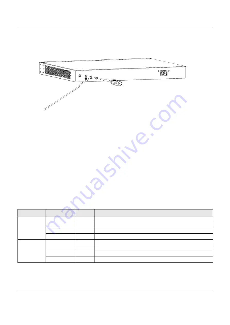
Warning! Connect the ground cable before you connect any other
cables or wiring.
Figure 21
Grounding
3.2.2 Power Connector
Note: Make sure you are using the correct power source as shown on the panel.
To connect power to the Switch, insert the female end of the power cord to the AC power receptacle
on the rear panel. Connect the other end of the supplied power cord to a power outlet. Make sure that
no objects obstruct the airflow of the fans (located on the side of the unit).
See
for information on the Switch’s power supply requirements.
3.3 LEDs
After you connect the power to the Switch, view the LEDs to ensure proper functioning of the Switch
and as an aid in troubleshooting.
Table 4 LED Descriptions
LED
COLOR
STATUS
DESCRIPTION
PWR
Green
On
The Switch is receiving power from the power module in the power slot.
Blinking
The Switch is returning to the custom default configuration settings.
Amber
On
The Switch is returning to its factory default configuration settings.
Off
The Switch is not receiving power from the power module in the power slot.
SYS
Green
On
The Switch is on and functioning properly.
Blinking
The Switch is rebooting and performing self-diagnostic tests.
Red
On
The Switch is functioning abnormally.
Off
The power is off or the Switch is not ready/malfunctioning.


