background image

P-660H/HW-T Series User’ Guide

Introduction to DSL

40

Introduction to DSL

DSL (Digital Subscriber Line) technology enhances the data capacity of the existing twisted-
pair wire that runs between the local telephone company switching offices and most homes 
and offices. While the wire itself can handle higher frequencies, the telephone switching 
equipment is designed to cut off signals above 4,000 Hz to filter noise off the voice line, but 
now everybody is searching for ways to get more bandwidth to improve access to the Web - 
hence DSL technologies. 

There are actually seven types of DSL service, ranging in speeds from 16 Kbits/sec to 52 
Mbits/sec. The services are either symmetrical (traffic flows at the same speed in both 
directions), or asymmetrical (the downstream capacity is higher than the upstream capacity). 
Asymmetrical services (ADSL) are suitable for Internet users because more information is 
usually downloaded than uploaded. For example, a simple button click in a web browser can 
start an extended download that includes graphics and text.

As data rates increase, the carrying distance decreases. That means that users who are beyond 
a certain distance from the telephone company’s central office may not be able to obtain the 
higher speeds.

A DSL connection is a point-to-point dedicated circuit, meaning that the link is always up and 
there is no dialing required. 

Introduction to ADSL

It is an asymmetrical technology, meaning that the downstream data rate is much higher than 
the upstream data rate. As mentioned, this works well for a typical Internet session in which 
more information is downloaded, for example, from Web servers, than is uploaded. ADSL 
operates in a frequency range that is above the frequency range of voice services, so the two 
systems can operate over the same cable. 

Summary of Contents for P-660H Series

Page 1: ...P 660H T Series ADSL2 4 port Security Gateway P 660HW T Series 802 11g Wireless ADSL2 4 port Security Gateway User s Guide Version 3 40 2 2006 ...

Page 2: ......

Page 3: ... ZyXEL Communications Corporation All rights reserved Disclaimer ZyXEL does not assume any liability arising out of the application or use of any products or software described herein Neither does it convey any license under its patent rights nor the patent rights of others ZyXEL further reserves the right to make changes in any products described herein without notice This publication is subject ...

Page 4: ...occur in a particular installation If this equipment does cause harmful interference to radio television reception which can be determined by turning the equipment off and on the user is encouraged to try to correct the interference by one or more of the following measures Reorient or relocate the receiving antenna Increase the separation between the equipment and the receiver Connect the equipmen...

Page 5: ...ther antenna or transmitter ZyXEL Communications Corporation declared that Prestige 660HW T1 is limited in CH1 11 from 2400 to 2483 5 MHz by specified firmware controlled in USA Certifications Go to www zyxel com 1 Select your product from the drop down list box on the ZyXEL home page to go to that product s page 2 Select the certification you wish to view from this page ...

Page 6: ... supply is damaged remove it from the power outlet Do NOT attempt to repair the power supply Contact your local vendor to order a new power supply Place connecting cables carefully so that no one will step on them or stumble over them Do NOT allow anything to rest on the power cord and do NOT locate the product where anyone can walk on the power cord If you wall mount your device make sure that no...

Page 7: ...d by an act of God or subjected to abnormal working conditions Note Repair or replacement as provided under this warranty is the exclusive remedy of the purchaser This warranty is in lieu of all other warranties express or implied including any implied warranty of merchantability or fitness for a particular use or purpose ZyXEL shall in no event be held liable for indirect or consequential damages...

Page 8: ...enmark sales zyxel dk 45 39 55 07 07 FINLAND support zyxel fi 358 9 4780 8411 www zyxel fi ZyXEL Communications Oy Malminkaari 10 00700 Helsinki Finland sales zyxel fi 358 9 4780 8448 FRANCE info zyxel fr 33 4 72 52 97 97 www zyxel fr ZyXEL France 1 rue des Vergers Bat 1 C 69760 Limonest France 33 4 72 52 19 20 GERMANY support zyxel de 49 2405 6909 0 www zyxel de ZyXEL Deutschland GmbH Adenauerstr...

Page 9: ...upport zyxel se 46 31 744 7700 www zyxel se ZyXEL Communications A S Sjöporten 4 41764 Göteborg Sweden sales zyxel se 46 31 744 7701 UKRAINE support ua zyxel com 380 44 247 69 78 www ua zyxel com ZyXEL Ukraine 13 Pimonenko Str Kiev 04050 Ukraine sales ua zyxel com 380 44 494 49 32 UNITED KINGDOM support zyxel co uk 44 1344 303044 08707 555779 UK only www zyxel co uk ZyXEL Communications UK Ltd 11 ...

Page 10: ...P 660H HW T Series User Guide 9 Customer Support ...

Page 11: ...To Know Your Prestige 42 1 1 Introducing the Prestige 42 1 2 Features 42 1 2 1 Wireless Features P 660HW 45 1 3 Applications for the Prestige 46 1 3 1 Protected Internet Access 46 1 3 2 LAN to LAN Application 46 1 4 Front Panel LEDs 46 1 5 Hardware Connection 47 Chapter 2 Introducing the Web Configurator 48 2 1 Web Configurator Overview 48 2 1 1 Accessing the Web Configurator 48 2 1 2 Resetting th...

Page 12: ...orks 67 4 3 Configuring LAN 68 Chapter 5 Wireless LAN 70 5 1 Wireless LAN Introduction 70 5 2 Wireless Security Overview 70 5 2 1 Encryption 70 5 2 2 Authentication 70 5 2 3 Restricted Access 71 5 2 4 Hide Prestige Identity 71 5 3 The Main Wireless LAN Screen 71 5 4 Configuring the Wireless Screen 73 5 4 1 WEP Encryption 73 5 5 Configuring MAC Filters 75 5 6 Introduction to WPA 77 5 6 1 WPA PSK Ap...

Page 13: ...on 92 6 1 4 3 IP Assignment with ENET ENCAP Encapsulation 92 6 1 5 Nailed Up Connection PPP 92 6 1 6 NAT 92 6 2 Metric 92 6 3 PPPoE Encapsulation 93 6 4 Traffic Shaping 93 6 5 Zero Configuration Internet Access 94 6 6 The Main WAN Screen 95 6 7 Configuring WAN Setup 95 6 8 Traffic Redirect 98 6 9 Configuring WAN Backup 99 Chapter 7 Network Address Translation NAT Screens 102 7 1 NAT Overview 102 7...

Page 14: ...Stateful Inspection Firewalls 119 10 3 Introduction to ZyXEL s Firewall 119 10 3 1 Denial of Service Attacks 120 10 4 Denial of Service 120 10 4 1 Basics 120 10 4 2 Types of DoS Attacks 121 10 4 2 1 ICMP Vulnerability 123 10 4 2 2 Illegal Commands NetBIOS and SMTP 123 10 4 2 3 Traceroute 124 10 5 Stateful Inspection 124 10 5 1 Stateful Inspection Process 125 10 5 2 Stateful Inspection and the Pres...

Page 15: ... Rules 138 11 7 Customized Services 141 11 8 Configuring A Customized Service 141 11 9 Example Firewall Rule 142 11 10 Predefined Services 146 11 11 Anti Probing 148 11 12 DoS Thresholds 149 11 12 1 Threshold Values 150 11 12 2 Half Open Sessions 150 11 12 2 1 TCP Maximum Incomplete and Blocking Time 150 11 12 3 Configuring Firewall Thresholds 151 Chapter 12 Content Filtering 154 12 1 Content Filt...

Page 16: ...ges 179 15 4 1 Example E mail Log 180 Chapter 16 Media Bandwidth Management Advanced Setup 182 16 1 Media Bandwidth Management Overview 182 16 2 Bandwidth Classes and Filters 182 16 3 Proportional Bandwidth Allocation 183 16 4 Bandwidth Management Usage Examples 183 16 4 1 Application based Bandwidth Management Example 183 16 4 2 Subnet based Bandwidth Management Example 183 16 4 3 Application and...

Page 17: ... 17 6 1 General Diagnostic 202 17 6 2 DSL Line Diagnostic 203 17 7 Firmware Upgrade 205 Chapter 18 Introducing the SMT 208 18 1 SMT Introduction 208 18 1 1 Procedure for SMT Configuration via Telnet 208 18 1 2 Entering Password 208 18 1 3 Prestige SMT Menus Overview 209 18 2 Navigating the SMT Interface 210 18 2 1 System Management Terminal Interface Summary 211 18 3 Changing the System Password 2...

Page 18: ...uration 233 Chapter 24 Remote Node Configuration 236 24 1 Remote Node Setup Overview 236 24 2 Remote Node Setup 236 24 2 1 Remote Node Profile 236 24 2 2 Encapsulation and Multiplexing Scenarios 237 24 2 2 1 Scenario 1 One VC Multiple Protocols 237 24 2 2 2 Scenario 2 One VC One Protocol IP 237 24 2 2 3 Scenario 3 Multiple VCs 237 24 2 3 Outgoing Authentication Protocol 239 24 3 Remote Node Networ...

Page 19: ...Server behind NAT 260 27 5 General NAT Examples 261 27 5 1 Example 1 Internet Access Only 262 27 5 2 Example 2 Internet Access with an Inside Server 262 27 5 3 Example 3 Multiple Public IP Addresses With Inside Servers 263 27 5 4 Example 4 NAT Unfriendly Application Programs 267 Chapter 28 Enabling the Firewall 270 28 1 Remote Management and the Firewall 270 28 2 Access Methods 270 28 3 Enabling t...

Page 20: ... and Diagnosis 296 32 1 Overview 296 32 2 System Status 296 32 3 System Information 298 32 3 1 System Information 298 32 3 2 Console Port Speed 299 32 4 Log and Trace 300 32 4 1 Viewing Error Log 300 32 4 2 Syslog and Accounting 301 32 5 Diagnostic 303 Chapter 33 Firmware and Configuration File Maintenance 306 33 1 Filename Conventions 306 33 2 Backup Configuration 307 33 2 1 Backup Configuration ...

Page 21: ...4 1 Command Interpreter Mode 318 34 2 Call Control Support 319 34 2 1 Budget Management 319 34 3 Time and Date Setting 320 34 3 1 Resetting the Time 322 Chapter 35 Remote Management 324 35 1 Remote Management Overview 324 35 2 Remote Management 324 35 2 1 Remote Management Setup 324 35 2 2 Remote Management Limitations 325 35 3 Remote Management and NAT 326 35 4 System Timeout 326 Chapter 36 IP Po...

Page 22: ...38 4 2 ActiveX Controls in Internet Explorer 351 Appendix A Product Specifications 354 Appendix B Wall mounting Instructions 358 Appendix C Setting up Your Computer s IP Address 360 Windows 95 98 Me 360 Windows 2000 NT XP 363 Macintosh OS 8 9 368 Macintosh OS X 370 Linux 371 Figure 256 Verifying Settings 375 Appendix D IP Subnetting 376 IP Addressing 376 IP Classes 376 Subnet Masks 377 Subnetting ...

Page 23: ...ecting a POTS Splitter 398 Telephone Microfilters 398 Prestige With ISDN 399 Appendix J PPPoE 402 PPPoE in Action 402 Benefits of PPPoE 402 Traditional Dial up Scenario 402 How PPPoE Works 403 Prestige as a PPPoE Client 403 Appendix K Wireless LANs 404 Wireless LAN Topologies 404 Channel 406 RTS CTS 406 Fragmentation Threshold 407 Preamble Type 408 IEEE 802 1x 409 RADIUS 409 Types of Authenticatio...

Page 24: ... Contents Log Command Example 429 Appendix M Internal SPTGEN 430 Internal SPTGEN Overview 430 The Configuration Text File Format 430 Internal SPTGEN FTP Download Example 431 Internal SPTGEN FTP Upload Example 432 Command Examples 453 Index 456 ...

Page 25: ...ration 59 Figure 15 Internet Access Wizard Setup Connection Tests 60 Figure 16 LAN and WAN IP Addresses 62 Figure 17 Any IP Example 67 Figure 18 LAN Setup 68 Figure 19 Wireless LAN 72 Figure 20 Wireless Security Methods 73 Figure 21 Wireless Screen 74 Figure 22 MAC Filter 76 Figure 23 WPA PSK Authentication 78 Figure 24 WPA with RADIUS Application Example2 79 Figure 25 Wireless LAN 802 1x WPA No A...

Page 26: ...Custom Port Example 144 Figure 60 Firewall Example Edit Rule Select Customized Services 145 Figure 61 Firewall Example Rule Summary My Service 146 Figure 62 Firewall Anti Probing 149 Figure 63 Firewall Threshold 151 Figure 64 Content Filtering 154 Figure 65 Content Filter Keyword 155 Figure 66 Content Filter Schedule 156 Figure 67 Content Filter Trusted 157 Figure 68 Telnet Configuration on a TCP ...

Page 27: ...dwidth Management Monitor 194 Figure 99 System Status 197 Figure 100 System Status Show Statistics 199 Figure 101 DHCP Table 200 Figure 102 Any IP Table 201 Figure 103 Association List 202 Figure 104 Diagnostic General 203 Figure 105 Diagnostic DSL Line 204 Figure 106 Firmware Upgrade 205 Figure 107 Network Temporarily Disconnected 206 Figure 108 Error Message 206 Figure 109 Login Screen 209 Figur...

Page 28: ...oute 252 Figure 142 Menu 4 Applying NAT for Internet Access 255 Figure 143 Applying NAT in Menus 4 11 3 255 Figure 144 Menu 15 NAT Setup 256 Figure 145 Menu 15 1 Address Mapping Sets 257 Figure 146 Menu 15 1 255 SUA Address Mapping Rules 257 Figure 147 Menu 15 1 1 First Set 258 Figure 148 Menu 15 1 1 1 Editing Configuring an Individual Rule in a Set 259 Figure 149 Menu 15 2 NAT Server Setup 260 Fi...

Page 29: ...tem Maintenance 296 Figure 189 Menu 24 1 System Maintenance Status 297 Figure 190 Menu 24 2 System Information and Console Port Speed 298 Figure 191 Menu 24 2 1 System Maintenance Information 299 Figure 192 Menu 24 2 2 System Maintenance Change Console Port Speed 300 Figure 193 Menu 24 3 System Maintenance Log and Trace 300 Figure 194 Sample Error and Information Messages 301 Figure 195 Menu 24 3 ...

Page 30: ...232 Internet Options Security 352 Figure 233 Security Setting ActiveX Controls 353 Figure 234 Wall mounting Example 358 Figure 235 WIndows 95 98 Me Network Configuration 361 Figure 236 Windows 95 98 Me TCP IP Properties IP Address 362 Figure 237 Windows 95 98 Me TCP IP Properties DNS Configuration 363 Figure 238 Windows XP Start Menu 364 Figure 239 Windows XP Control Panel 364 Figure 240 Windows X...

Page 31: ...th ISDN 399 Figure 263 Single Computer per Router Hardware Configuration 403 Figure 264 Prestige as a PPPoE Client 403 Figure 265 Peer to Peer Communication in an Ad hoc Network 404 Figure 266 Basic Service Set 405 Figure 267 Infrastructure WLAN 406 Figure 268 RTS CTS 407 Figure 269 Displaying Log Categories Example 428 Figure 270 Displaying Log Parameters Example 428 Figure 271 Configuration Text...

Page 32: ...P 660H HW T Series User Guide 31 List of Figures ...

Page 33: ...eless LAN 802 1x WPA No Access Authentication 80 Table 16 Wireless LAN 802 1x WPA 802 1x 81 Table 17 Wireless LAN 802 1x WPA WPA 83 Table 18 Wireless LAN 802 1x WPA WPA PSK 84 Table 19 Local User Database 86 Table 20 RADIUS 87 Table 21 WAN 95 Table 22 WAN Setup 96 Table 23 WAN Backup 100 Table 24 NAT Definitions 102 Table 25 NAT Mapping Types 105 Table 26 Services and Port Numbers 106 Table 27 NAT...

Page 34: ...dth Management Class Setup 190 Table 58 Media Bandwidth Management Class Configuration 191 Table 59 Services and Port Numbers 192 Table 60 Media Bandwidth Management Statistics 193 Table 61 Media Bandwidth Management Monitor 194 Table 62 System Status 197 Table 63 System Status Show Statistics 199 Table 64 DHCP Table 200 Table 65 Any IP Table 201 Table 66 Association List 202 Table 67 Diagnostic G...

Page 35: ...nent Virtual Circuits 289 Table 102 Menu 23 2 System Security RADIUS Server 291 Table 103 Menu 23 4 System Security IEEE 802 1x 293 Table 104 Menu 14 1 Edit Dial in User 295 Table 105 Menu 24 1 System Maintenance Status 297 Table 106 Menu 24 2 1 System Maintenance Information 299 Table 107 Menu 24 3 2 System Maintenance Syslog and Accounting 301 Table 108 Menu 24 4 System Maintenance Menu Diagnost...

Page 36: ... Table 143 System Maintenance Logs 414 Table 144 System Error Logs 415 Table 145 Access Control Logs 415 Table 146 TCP Reset Logs 416 Table 147 Packet Filter Logs 416 Table 148 ICMP Logs 417 Table 149 CDR Logs 417 Table 150 PPP Logs 417 Table 151 UPnP Logs 418 Table 152 Content Filtering Logs 418 Table 153 Attack Logs 419 Table 154 IPSec Logs 420 Table 155 IKE Logs 420 Table 156 PKI Logs 423 Table...

Page 37: ...erver Setup SMT Menu 15 442 Table 169 Menu 21 1 Filter Set 1 SMT Menu 21 1 444 Table 170 Menu 21 1 Filer Set 2 SMT Menu 21 1 447 Table 171 Menu 23 System Menus SMT Menu 23 452 Table 172 Menu 24 11 Remote Management Control SMT Menu 24 11 453 Table 173 Command Examples 453 ...

Page 38: ...P 660H HW T Series User Guide 37 List of Tables ...

Page 39: ...ace to configure your Prestige Not all features can be configured through all interfaces Syntax Conventions Enter means for you to type one or more characters Select or Choose means for you to use one predefined choices The SMT menu titles and labels are in Bold Times New Roman font Predefined field choices are in Bold Arial font Command and arrow keys are enclosed in square brackets ENTER means t...

Page 40: ...al support documentation User Guide Feedback Help us help you E mail all User Guide related comments questions or suggestions for improvement to techwriters zyxel com tw or send regular mail to The Technical Writing Team ZyXEL Communications Corp 6 Innovation Road II Science Based Industrial Park Hsinchu 300 Taiwan Thank you Graphics Icons Key Prestige Computer Notebook computer Server DSLAM Firew...

Page 41: ...pstream capacity Asymmetrical services ADSL are suitable for Internet users because more information is usually downloaded than uploaded For example a simple button click in a web browser can start an extended download that includes graphics and text As data rates increase the carrying distance decreases That means that users who are beyond a certain distance from the telephone company s central o...

Page 42: ...P 660H HW T Series User Guide 41 Introduction to DSL ...

Page 43: ...a device that works over ISDN Integrated Services Digital Network Models ending in 7 denote a device that works over T ISDN UR 2 Note Only use firmware for your Prestige s specific model Refer to the label on the bottom of your Prestige The DSL RJ 11 ADSL over POTS models or RJ 45 ADSL over ISDN models connects to your ADSL enabled telephone line The Prestige is compatible with the ADSL ADSL2 ADSL...

Page 44: ... Internet and the Prestige without changing the network settings such as IP address and subnet mask of the computer when the IP addresses of the computer and the Prestige are not in the same subnet Firewall The Prestige is a stateful inspection firewall with DoS Denial of Service protection By default when the firewall is activated all incoming traffic from the WAN to the LAN is blocked unless it ...

Page 45: ...work for example a public IP address used on the Internet Dynamic DNS Support With Dynamic DNS support you can have a static hostname alias for a dynamic IP address allowing the host to be more easily accessible from various locations on the Internet You must register for this service with a Dynamic DNS service provider DHCP DHCP Dynamic Host Configuration Protocol allows the individual clients co...

Page 46: ...ng that you can have both IEEE 802 11b and IEEE 802 11g wireless clients in the same wireless network Note The Prestige may be prone to RF Radio Frequency interference from other 2 4 GHz devices such as microwave ovens wireless phones Bluetooth enabled devices and other wireless LANs Wi Fi Protected Access Wi Fi Protected Access WPA is a subset of the IEEE 802 11i security specification standard K...

Page 47: ...reless clients access to your network resources The Prestige provides protection from attacks by Internet hackers By default the firewall blocks all incoming traffic from the WAN The firewall supports TCP UDP inspection and DoS Denial of Services detection and prevention as well as real time alerts reports and logs Figure 1 Protected Internet Access Applications ss 1 3 2 LAN to LAN Application You...

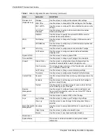
Page 48: ...ige is too low Off The system is not ready or has malfunctioned LAN Green On The Prestige has a successful 10 100Mb Ethernet connection Blinking The Prestige is sending receiving data Off The LAN is not connected WLAN P 660HW only Green On The Prestige is ready but is not sending receiving data through the wireless LAN Blinking The Prestige is sending receiving data through the wireless LAN Off Th...

Page 49: ... XP SP Service Pack 2 JavaScripts enabled by default Java permissions enabled by default See the chapter on troubleshooting if you need to make sure these functions are allowed in Internet Explorer 2 1 1 Accessing the Web Configurator Note Even though you can connect to the Prestige wirelessly it is recommended that you connect your computer to a LAN port for initial configuration 1 Make sure your...

Page 50: ...Note The Prestige automatically times out after five minutes of inactivity Simply log back into the Prestige if this happens to you 2 1 2 Resetting the Prestige If you forget your password or cannot access the web configurator you will need to use the RESET button at the back of the Prestige to reload the factory default configuration file This means that you will lose all configurations that you ...

Page 51: ...ad a configuration file Click Site Map to go to the Site Map screen Click Logout in the navigation panel when you have finished a Prestige management session Figure 6 Web Configurator Site Map Screen Note Click the icon located in the top right corner of most screens to view embedded help Table 3 Web Configurator Screens Summary LINK SUB LINK FUNCTION Wizard Setup Connection Setup Use these screen...

Page 52: ...to apply the rule Rule Summary This screen shows a summary of the firewall rules and allows you to edit add a firewall rule Anti Probing Use this screen to change your anti probing settings Threshold Use this screen to configure the threshold for DoS attacks Content Filter Keyword Use this screen to block sites containing certain keywords in the URL Schedule Use this screen to set the days and tim...

Page 53: ...tion Protocol related information and is READ ONLY Any IP Table Use this screen to view the IP and MAC addresses of LAN computers communicating with the Prestige Wireless LAN P 660HW only Association List This screen displays the MAC address es of the wireless stations that are currently associating with the Prestige Diagnostic General These screens display information to help you identify problem...

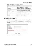
Page 54: ...d Type the default password or the existing password you use to access the system in this field New Password Type the new password in this field Retype to Confirm Type the new password again in this field Apply Click Apply to save your changes back to the Prestige Cancel Click Cancel to begin configuring this screen afresh ...

Page 55: ...troduction Use the Wizard Setup screens to configure your system for Internet access with the information given to you by your ISP Note See the advanced menu chapters for background information on these fields 3 1 1 Internet Access Wizard Setup 1 In the SITE MAP screen click Wizard Setup to display the first wizard screen Figure 8 Internet Access Wizard Setup ISP Parameters The following table des...

Page 56: ...drop down list box Choices vary depending on what you select in the Mode field If you select Bridge in the Mode field select either PPPoA or RFC 1483 If you select Routing in the Mode field select PPPoA RFC 1483 ENET ENCAP or PPPoE Multiplex Select the multiplexing method used by your ISP from the Multiplex drop down list box either VC based or LLC based Virtual Circuit ID VPI Virtual Path Identif...

Page 57: ...w Connection Select Connect on Demand when you don t want the connection up all the time and specify an idle time out in seconds in the Max Idle Timeout field The default setting selects Connection on Demand with 0 as the idle time out which means the Internet session will not timeout Select Nailed Up Connection when you want your connection up all the time The Prestige will try to bring up the co...

Page 58: ...matically if you have a dynamic IP address otherwise select Static IP Address and type your ISP assigned IP address in the IP Address text box below Subnet Mask Enter a subnet mask in dotted decimal notation Refer to the appendices to calculate a subnet mask If you are implementing subnetting ENET ENCAP Gateway You must specify a gateway IP address supplied by your ISP when you use ENET ENCAP in t...

Page 59: ... and type your ISP assigned IP address in the IP Address text box below Connection Select Connect on Demand when you don t want the connection up all the time and specify an idle time out in seconds in the Max Idle Timeout field The default setting selects Connection on Demand with 0 as the idle time out which means the Internet session will not timeout Select Nailed Up Connection when you want yo...

Page 60: ...n the Prestige click Change LAN Configurations Otherwise click Save Settings to save the configuration and skip to the section 3 13 Figure 13 Internet Access Wizard Setup Third Screen If you want to change your Prestige LAN settings click Change LAN Configuration to display the screen as shown next Figure 14 Internet Access Wizard Setup LAN Configuration ...

Page 61: ...P address of your Prestige in dotted decimal notation for example 192 168 1 1 factory default If you changed the Prestige s LAN IP address you must use the new IP address if you want to access the web configurator again LAN Subnet Mask Enter a subnet mask in dotted decimal notation DHCP DHCP Server From the DHCP Server drop down list box select On to allow your Prestige to assign IP addresses an I...

Page 62: ...P 660H HW T Series User Guide 61 Chapter 3 Wizard Setup for Internet Access ...

Page 63: ... the immediate area usually the same building or floor of a building The LAN screens can help you configure a LAN DHCP server and manage IP addresses See Section 4 3 on page 68 to configure the LAN screens 4 1 1 LANs WANs and the Prestige The actual physical connection determines whether the Prestige ports are LAN or WAN ports There are two separate IP networks one inside the LAN network and the o...

Page 64: ...s up If your ISP gives you the DNS server addresses enter them in the DNS Server fields in DHCP Setup otherwise leave them blank Some ISP s choose to pass the DNS servers using the DNS server extensions of PPP IPCP IP Control Protocol after the connection is up If your ISP did not give you explicit DNS servers chances are the DNS servers are conveyed through IPCP negotiation The Prestige supports ...

Page 65: ...then most likely you have a single user account and the ISP will assign you a dynamic IP address when the connection is established If this is the case it is recommended that you select a network number from 192 168 0 0 to 192 168 255 0 and you must enable the Network Address Translation NAT feature of the Prestige The Internet Assigned Number Authority IANA reserved this block of addresses specif...

Page 66: ...lines above For more information on address assignment please refer to RFC 1597 Address Allocation for Private Internets and RFC 1466 Guidelines for Management of IP Address Space 4 2 2 RIP Setup RIP Routing Information Protocol allows a router to exchange routing information with other routers The RIP Direction field controls the sending and receiving of RIP packets When set to Both the Prestige ...

Page 67: ...all directly connected networks to gather group membership After that the Prestige periodically updates this information IP multicasting can be enabled disabled on the Prestige LAN and or WAN interfaces in the web configurator LAN WAN Select None to disable IP multicasting on these interfaces 4 2 4 Any IP Traditionally you must set the IP addresses and the subnet masks of a computer and the Presti...

Page 68: ...uter tries to access the Internet for the first time through the Prestige 1 When a computer which is in a different subnet first attempts to access the Internet it sends packets to its default gateway which is not the Prestige by looking at the MAC address in its ARP table 2 When the computer cannot locate the default gateway an ARP request is broadcast on the LAN 3 The Prestige receives the ARP r...

Page 69: ...ult gateway and DNS servers to Windows 95 Windows NT and other systems that support the DHCP client If set to None the DHCP server will be disabled If set to Relay the Prestige acts as a surrogate DHCP server and relays DHCP requests and responses between the remote server and the clients Enter the IP address of the actual remote DHCP server in the Remote DHCP Server field in this case When DHCP i...

Page 70: ...the RIP version from RIP 1 RIP 2B and RIP 2M Multicast IGMP Internet Group Multicast Protocol is a network layer protocol used to establish membership in a multicast group The Prestige supports both IGMP version 1 IGMP v1 and IGMP v2 Select None to disable it Any IP Setup Select the Active check box to enable the Any IP feature This allows a computer to access the Internet without changing the net...

Page 71: ...s points and the wired network Wireless security methods available on the Prestige are data encryption wireless client authentication restricting access by device MAC address and hiding the Prestige identity 5 2 1 Encryption Use WPA security if you have WPA aware wireless clients and a RADIUS server WPA has user authentication and improved data encryption over WEP Use WPA PSK if you have WPA aware...

Page 72: ... 2 3 Restricted Access The MAC Filter screen allows you to configure the AP to give exclusive access to devices Allow Association or exclude them from accessing the AP Deny Association 5 2 4 Hide Prestige Identity If you hide the ESSID then the Prestige cannot be seen when a wireless client scans for local APs The trade off for the extra security of hiding the Prestige may be inconvenience for som...

Page 73: ... If you configure WEP you can t configure WPA or WPA PSK MAC Filter Click this link to go to a screen where you can restrict access to your wireless network by MAC address 802 1x WPA Click this link to go to a screen where you can configure WPA or WPA PSK You can also configure 802 1x wireless client authentication in this screen RADIUS Click this link to go to a screen where you can configure the...

Page 74: ... Configuring the Wireless Screen 5 4 1 WEP Encryption WEP encryption scrambles the data transmitted between the wireless stations and the access points to keep network communications private It encrypts unicast and multicast communications in a network Both the wireless stations and the access points must use the same WEP key Your Prestige allows you to configure up to four 64 bit 128 bit or 256 b...

Page 75: ...cluding spaces alphabetic characters are case sensitive Hide ESSID Select Yes to hide the ESSID in so a station cannot obtain the ESSID through AP scanning Select No to make the ESSID visible so a station can obtain the ESSID through AP scanning Channel ID The radio frequency used by IEEE 802 11a b or g wireless devices is called a channel Select a channel from the drop down list box RTS CTS Thres...

Page 76: ...ate four different WEP keys At the time of writing you cannot use passphrase to generate 256 bit WEP keys Generate After you enter the passphrase click Generate to have the Prestige generate four different WEP keys automatically The keys display in the fields below WEP Encryption WEP Wired Equivalent Privacy encrypts data frames before transmitting over the wireless network Select Disable to allow...

Page 77: ...e describes the fields in this menu Table 14 MAC Filter LABEL DESCRIPTION Active Select Yes from the drop down list box to enable MAC address filtering Action Define the filter action for the list of MAC addresses in the MAC Address table Select Deny Association to block access to the router MAC addresses not listed will be allowed to access the Prestige Select Allow Association to permit access t...

Page 78: ...t enter identical passwords into the AP and all wireless clients The Pre Shared Key PSK must be between 8 and 63 printable characters including spaces alphabetic characters are case sensitive 2 The AP checks each client s password and only allows it to join the network if the passwords match 3 The AP derives and distributes keys to the wireless clients 4 The AP and wireless clients use the TKIP en...

Page 79: ...system wired link to the LAN 1 The AP passes the wireless client s authentication request to the RADIUS server 2 The RADIUS server then checks the user s identification against its database and grants or denies network access accordingly 3 The RADIUS server distributes a Pairwise Master Key PMK key to the AP that then sets up a key hierarchy and management system using the pair wise key to dynamic...

Page 80: ...ity to Windows XP s built in Zero Configuration wireless client However you must run Windows XP to use it See Section 5 7 3 on page 82 and Section 5 7 4 on page 84 for configuration instruction 5 7 Configuring IEEE 802 1x and WPA To change your Prestige s authentication settings click the Wireless LAN link under Advanced Setup and then the 802 1x WPA tab The screen varies by the key management pro...

Page 81: ... network select a control method from the drop down list box Choose from No Access Allowed No Authentication Required and Authentication Required No Access Allowed blocks all wireless stations access to the wired network No Authentication Required allows all wireless stations access to the wired network without entering usernames and passwords This is the default setting Authentication Required me...

Page 82: ...creen Figure 27 Wireless LAN 802 1x WPA 802 1xl The following table describes the labels in this screen Table 16 Wireless LAN 802 1x WPA 802 1x LABEL DESCRIPTION Wireless Port Control To control wireless station access to the wired network select a control method from the drop down list box Choose from No Authentication Required Authentication Required and No Access Allowed The following fields ar...

Page 83: ...ication Databases The authentication database contains wireless station login information The local user database is the built in database on the Prestige The RADIUS is an external server Use this drop down list box to select which database the Prestige should use first to authenticate a wireless station Before you specify the priority make sure you have set up the corresponding database correctly...

Page 84: ...group traffic if the Key Management Protocol is WPA and WPA Mixed Mode is disabled WEP is used automatically if you have enabled WPA Mixed Mode All unicast traffic is automatically encrypted by TKIP when WPA or WPA PSK Key Management Protocol is selected WPA Group Key Update Timer The WPA Group Key Update Timer is the rate at which the AP if using WPA PSK key management or RADIUS server if using W...

Page 85: ...agement Protocol Choose WPA PSK in this field Pre Shared Key The encryption mechanisms used for WPA and WPA PSK are the same The only difference between the two is that WPA PSK uses a simple common password instead of user specific credentials Type a pre shared key from 8 to 63 printable characters including spaces alphabetic characters are case sensitive WPA Mixed Mode The Prestige can operate in...

Page 86: ...ess LAN Local User Database The screen appears as shown Group Data Privacy Group Data Privacy allows you to choose TKIP recommended or WEP for broadcast and multicast group traffic if the Key Management Protocol is WPA and WPA Mixed Mode is disabled WEP is used automatically if you have enabled WPA Mixed Mode All unicast traffic is automatically encrypted by TKIP when WPA or WPA PSK Key Management...

Page 87: ...er name of up to 31 alphanumeric characters case sensitive hyphens and underscores _ if you re using MD5 encryption and maximum 14 if you re using PEAP Password Enter a password of up to 31 printable characters including spaces alphabetic characters are case sensitive if you re using MD5 encryption and maximum 14 if you re using PEAP Back Click Back to go to the main wireless LAN setup screen Appl...

Page 88: ...tted decimal notation Port Number The default port of the RADIUS server for authentication is 1812 You need not change this value unless your network administrator instructs you to do so with additional information Shared Secret Enter a password up to 31 alphanumeric characters as the key to be shared between the external authentication server and the access points The key is not sent over the net...

Page 89: ...a password up to 31 alphanumeric characters as the key to be shared between the external accounting server and the access points The key is not sent over the network This key must be the same on the external accounting server and the Prestige Back Click Back to go to the main wireless LAN setup screen Apply Click Apply to save these settings back to the Prestige Cancel Click Cancel to begin config...

Page 90: ...P 660H HW T Series User Guide 89 Chapter 5 Wireless LAN ...

Page 91: ...ateway field in the second wizard screen You can get this information from your ISP 6 1 1 2 PPP over Ethernet PPPoE provides access control and billing functionality in a manner similar to dial up services using PPP The Prestige bridges a PPP session over Ethernet PPP over Ethernet RFC 2516 from your computer to an ATM PVC Permanent Virtual Circuit which connects to ADSL Access Concentrator where ...

Page 92: ...ing information being contained in each packet header Despite the extra bandwidth and processing overhead this method may be advantageous if it is not practical to have a separate VC for each carried protocol for example if charging heavily depends on the number of simultaneous VCs 6 1 3 VPI and VCI Be sure to use the correct Virtual Path Identifier VPI and Virtual Channel Identifier VCI numbers a...

Page 93: ...n is down A nailed up connection can be very expensive for obvious reasons Do not specify a nailed up connection unless your telephone company offers flat rate service or you need a constant connection and the cost is of no concern 6 1 6 NAT NAT Network Address Translation NAT RFC 1631 is the translation of the IP address of a host in a packet for example the source address of an outgoing packet u...

Page 94: ...vice provider PPPoE offers an access and authentication method that works with existing access control systems for example Radius PPPoE provides a login and authentication method that the existing Microsoft Dial Up Networking software can activate and therefore requires no new learning or procedures for Windows users One of the benefits of PPPoE is the ability to let you access one of multiple net...

Page 95: ...s time more cells up to the MBS can be sent at the PCR again If the PCR SCR or MBS is set to the default of 0 the system will assign a maximum value that correlates to your upstream line rate The following figure illustrates the relationship between PCR SCR and MBS Figure 32 Example of Traffic Shaping 6 5 Zero Configuration Internet Access Once you turn on and connect the Prestige to a telephone j...

Page 96: ...n 6 7 Configuring WAN Setup To change your Prestige s WAN remote node settings click WAN and WAN Setup The screen differs by the encapsulation See Section 6 1 on page 90 for more information Table 21 WAN LINK DESCRIPTION WAN Setup Click this link to go to the screen where you can configure your Prestige for an Internet connection WAN Backup Click this link to go to the screen where you can configu...

Page 97: ...ds in this screen Table 22 WAN Setup LABEL DESCRIPTION Name Enter the name of your Internet Service Provider e g MyISP This information is for identification purposes only Mode Select Routing default from the drop down list box if your ISP allows multiple computers to share an Internet account Otherwise select Bridge ...

Page 98: ...ll Rate PCR This is the maximum rate at which the sender can send cells Type the PCR here Sustain Cell Rate The Sustain Cell Rate SCR sets the average cell rate long term that can be transmitted Type the SCR which must be less than the PCR Note that system default is 0 cells sec Maximum Burst Size Maximum Burst Size MBS refers to the maximum number of cells that can be sent at the peak rate Type t...

Page 99: ...e to NAT for application where NAT is not appropriate Disable PPPoE pass through if you do not need to allow hosts on the LAN to use PPPoE client software on their computers to connect to the ISP Subnet Mask ENET ENCAP encapsulation only Enter a subnet mask in dotted decimal notation Refer to the appendices to calculate a subnet mask If you are implementing subnetting ENET ENCAP Gateway ENET ENCAP...

Page 100: ...three logical networks with the Prestige itself as the gateway for each LAN network Put the protected LAN in one subnet Subnet 1 in the following figure and the backup gateway in another subnet Subnet 2 Configure filters that allow packets from the protected LAN Subnet 1 to the backup gateway Subnet 2 Figure 36 Traffic Redirect LAN Setup 6 9 Configuring WAN Backup To change your Prestige s WAN bac...

Page 101: ...er traffic redirect or dial backup you must configure at least one IP address here When using a WAN backup connection the Prestige periodically pings the addresses configured here and uses the other WAN backup connection if configured if there is no response Fail Tolerance Type the number of times 2 recommended that your Prestige may ping the IP addresses configured in the Check WAN IP Address fie...

Page 102: ...irect you must configure at least one Check WAN IP Address Metric This field sets this route s priority among the routes the Prestige uses The metric represents the cost of transmission A router determines the best route for transmission by choosing a path with the lowest cost RIP routing uses hop count as the measurement of cost with a minimum of 1 for directly connected networks The number must ...

Page 103: ...fers to the IP address of a host when the packet is in the local network while the global address refers to the IP address of the host when the same packet is traveling in the WAN side Note that inside outside refers to the location of a host while global local refers to the IP address of a host used in a packet Thus an inside local address ILA is the IP address of an inside host in a packet when ...

Page 104: ... 105 NAT offers the additional benefit of firewall protection With no servers defined your Prestige filters out all incoming inquiries thus preventing intruders from probing your network For more information on IP address translation refer to RFC 1631 The IP Network Address Translator NAT 7 1 3 How NAT Works Each packet has two addresses a source address and a destination address For outgoing pack...

Page 105: ...NAT Works 7 1 4 NAT Application The following figure illustrates a possible NAT application where three inside LANs logical LANs using IP Alias behind the Prestige can communicate with three distinct WAN networks More examples follow at the end of this chapter Figure 39 NAT Application With IP Alias ...

Page 106: ...ps the multiple local IP addresses to shared global IP addresses Many to Many No Overload In Many to Many No Overload mode the Prestige maps each local IP address to a unique global IP address Server This type allows you to specify inside servers of different services behind the NAT to be accessible to the outside world Port numbers do NOT change for One to One and Many to Many No Overload NAT map...

Page 107: ...t 80 and FTP on port 21 In some cases such as for unknown services or where one server can support more than one service for example both FTP and web service it might be better to specify a range of port numbers You can allocate a server IP address that corresponds to a port or a range of ports Many residential broadband ISP accounts do not allow you to run any server processes such as a Web or FT...

Page 108: ...st on the Internet IP address assigned by ISP Figure 40 Multiple Servers Behind NAT Example 7 4 Selecting the NAT Mode You must create a firewall rule in addition to setting up SUA NAT to allow traffic from the WAN to be forwarded through the Prestige Click NAT to open the following screen SMTP Simple Mail Transfer Protocol 25 DNS Domain Name System 53 Finger 79 HTTP Hyper Text Transfer protocol o...

Page 109: ...n page 106 for more information See Table 26 on page 106 for port numbers commonly used for particular services Table 27 NAT Mode LABEL DESCRIPTION None Select this radio button to disable NAT SUA Only Select this radio button if you have just one public WAN IP address for your Prestige The Prestige uses Address Mapping Set 1 in the NAT Edit SUA NAT Server Set screen Edit Details Click this link t...

Page 110: ...of ports enter the start port number here and the end port number in the End Port No field End Port No Enter a port number in this field To forward only one port enter the port number again in the Start Port No field above and then enter it again in this field To forward a series of ports enter the last port number in a series that begins with the port number in the Start Port No field above Serve...

Page 111: ...e your Prestige s address mapping settings click NAT Select Full Feature and click Edit Details to open the following screen Figure 43 Address Mapping Rules The following table describes the fields in this screen Table 29 Address Mapping Rules LABEL DESCRIPTION Local Start IP This is the starting Inside Local IP Address ILA Local IP addresses are N A for Server port mapping Local End IP This is th...

Page 112: ...e local IP addresses to one global IP address This is equivalent to SUA i e PAT port address translation ZyXEL s Single User Account feature that previous ZyXEL routers supported only M M Ov Overload Many to Many Overload mode maps multiple local IP addresses to shared global IP addresses MM No No Overload Many to Many No Overload mode maps each local IP address to unique global IP addresses Serve...

Page 113: ...ype allows you to specify inside servers of different services behind the NAT to be accessible to the outside world Local Start IP This is the starting local IP address ILA Local IP addresses are N A for Server port mapping Local End IP This is the end local IP address ILA If your rule is for all local IP addresses then enter 0 0 0 0 as the Local Start IP address and 255 255 255 255 as the Local E...

Page 114: ...13 Chapter 7 Network Address Translation NAT Screens Cancel Click Cancel to return to the previously saved settings Delete Click Delete to exit this screen without saving Table 30 Edit Address Mapping Rule continued LABEL DESCRIPTION ...

Page 115: ...u even if they don t know your IP address First of all you need to have registered a dynamic DNS account with www dyndns org This is for people with a dynamic IP from their ISP or DHCP server that would still like to have a domain name The Dynamic DNS service provider will give you a password or key 8 1 1 DYNDNS Wildcard Enabling the wildcard feature for your host causes yourhost dyndns org to be ...

Page 116: ...ovider This is the name of your Dynamic DNS service provider Host Names Type the domain name assigned to your Prestige by your Dynamic DNS provider E mail Address Type your e mail address User Type your user name Password Type the password assigned to you Enable Wildcard Select the check box to enable DYNDNS Wildcard Apply Click Apply to save your changes back to the Prestige Cancel Click Cancel t...

Page 117: ... screen to configure the Prestige s time and date settings 9 1 Configuring Time and Date To change your Prestige s time and date click Time And Date The screen appears as shown Use this screen to configure the Prestige s time based on your local time zone Figure 46 Time and Date The following table describes the fields in this screen ...

Page 118: ... the month and day that your daylight savings time starts on if you selected Daylight Savings End Date Enter the month and day that your daylight savings time ends on if you selected Daylight Savings Synchronize system clock with Time Server now Select this option to have your Prestige use the time server that you configured above to set its internal system clock Please wait for up to 60 seconds w...

Page 119: ... never be the only mechanism or method employed For a firewall to guard effectively you must design and deploy it appropriately This requires integrating the firewall into a broad information security policy In addition specific policies must be implemented within the firewall itself Refer to Section 11 5 on page 135 to configure default firewall settings Refer to Section 11 6 on page 136 to view ...

Page 120: ...strict access by screening data packets against defined access rules They make access control decisions based on IP address and protocol They also inspect the session data to assure the integrity of the connection and to adapt to dynamic protocols These firewalls generally provide the best speed and transparency however they may lack the granular application level access control or caching that so...

Page 121: ...red to automatically detect and thwart all known DoS attacks 10 4 1 Basics Computers share information over the Internet using a common language called TCP IP TCP IP in turn is a set of application protocols that perform specific functions An extension number called the TCP port or UDP port identifies these protocols such as HTTP Web FTP File Transfer Protocol POP3 E mail etc For example Web traff...

Page 122: ... hang or reboot Teardrop attack exploits weaknesses in the re assembly of IP packet fragments As data is transmitted through a network IP packets are often broken up into smaller chunks Each fragment looks like the original IP packet except that it contains an offset field that says for instance This fragment is carrying bytes 200 through 400 of the original non fragmented IP packet The Teardrop p...

Page 123: ...n as a backlog queue SYN ACKs are moved off the queue only when an ACK comes back or when an internal timer which is set at relatively long intervals terminates the three way handshake Once the queue is full the system will ignore all incoming SYN requests making the system unavailable for legitimate users Figure 49 SYN Flood In a LAND Attack hackers flood SYN packets into the network with a spoof...

Page 124: ... the intermediary network but will also congest the network of the spoofed source IP address known as the victim network This flood of broadcast traffic consumes all available bandwidth making communications impossible Figure 50 Smurf Attack 10 4 2 1 ICMP Vulnerability ICMP is an error reporting protocol that works in concert with IP The following ICMP types trigger an alert 10 4 2 2 Illegal Comma...

Page 125: ...er or firewall The Prestige blocks all IP Spoofing attempts 10 5 Stateful Inspection With stateful inspection fields of the packets are compared to packets that are already known to be trusted For example if you access some outside service the proxy server remembers things about your original request like the port number and source and destination addresses This remembering is called saving the st...

Page 126: ...rmine and record information about the state of the packet s connection This information is recorded in a new state table entry created for the new connection If there is not a firewall rule for this packet and it is not an attack then the settings in the Default Policy screen determine the action for this packet 4 Based on the obtained state information a firewall rule creates a temporary access ...

Page 127: ...wall rules is a very powerful tool Using custom rules it is possible to disable all firewall protection or block all access to the Internet Use extreme caution when creating or deleting firewall rules Test changes after creating them to make sure they work correctly Below is a brief technical description of how these connections are tracked Connections may either be defined by the upper protocols ...

Page 128: ...d in through the firewall simply because they are too dangerous and contain too little tracking information For instance ICMP redirect packets are never allowed in since they could be used to reroute traffic through attacking machines 10 5 5 Upper Layer Protocols Some higher layer protocols such as FTP and RealAudio utilize multiple network connections simultaneously In general terms they usually ...

Page 129: ...ckers to crack your system Turn your computer off when not in use Never give out a password or any sensitive information to an unsolicited telephone call or e mail Never e mail sensitive information such as passwords credit card information etc without encrypting the information first Never submit sensitive information via a web page unless the web site uses secure connections You can identify a s...

Page 130: ...work B If the filter blocks the traffic from A to B it also blocks the traffic from B to A Filters can not distinguish traffic originating from an inside host or an outside host by IP address To block allow IP trace route 10 7 2 Firewall The firewall inspects packet contents as well as their source and destination addresses Firewalls of this type employ an inspection module applicable to all proto...

Page 131: ... between inside host networks and outside host networks Remember that filters can not distinguish traffic originating from an inside host or an outside host by IP address The firewall performs better than filtering if you need to check many rules Use the firewall if you need routine e mail reports about your system or need to be alerted when attacks occur The firewall can block specific URL traffi...

Page 132: ...P 660H HW T Series User Guide 131 Chapter 10 Firewalls ...

Page 133: ...tion of travel of packets to which they apply Note The LAN includes both the LAN port and the WLAN By default the Prestige s stateful packet inspection allows packets traveling in the following directions LAN to LAN Router This allows computers on the LAN to manage the Prestige and communicate between networks or subnets connected to the LAN interface LAN to WAN By default the Prestige s stateful ...

Page 134: ...w Note Study these points carefully before configuring rules 11 3 1 Rule Checklist State the intent of the rule For example This restricts all IRC access from the LAN to the Internet Or This allows a remote Lotus Notes server to synchronize over the Internet to an inside Notes server 1 Is the intent of the rule to forward or block traffic 2 What direction of traffic does the rule apply to 3 What I...

Page 135: ...s 11 3 3 3 Source Address What is the connection s source address is it on the LAN WAN Is it a single IP a range of IPs or a subnet 11 3 3 4 Destination Address What is the connection s destination address is it on the LAN WAN Is it a single IP a range of IPs or a subnet 11 4 Connection Direction This section describes examples for firewall rules for connections going from LAN to WAN and from WAN ...

Page 136: ...il account that you specify in the Log Settings screen see the chapter on logs 11 5 Configuring Default Firewall Policy Click Firewall and then Default Policy to display the following screen Activate the firewall by selecting the Firewall Enabled check box as seen in the following screen Refer to Section 10 1 on page 118 for more information Figure 52 Firewall Default Policy The following table de...

Page 137: ...ts to which they apply For example LAN to LAN Router means packets traveling from a computer subnet on the LAN to either another computer subnet on the LAN interface of the Prestige or the Prestige itself Default Action Use the radio buttons to select whether to Block silently discard or Forward allow the passage of packets that are traveling in the selected direction Log Select the check box to c...

Page 138: ...fic traveling in the selected packet direction The firewall rules that you configure summarized below take priority over the general firewall action settings above Rule This is your firewall rule number The ordering of your rules is important as rules are applied in turn Click a rule s number to go to the Firewall Edit Rule screen to configure or edit a firewall rule Active This field displays whe...

Page 139: ...r a log is created when packets match this rule Enabled or not Disable Alert This field tells you whether this rule generates an alert Yes or not No when the rule is matched Insert Append Type the index number for where you want to put a rule For example if you type 6 your new rule becomes number 6 and the previous rule 6 if there is one becomes rule 7 Click Insert to add a new firewall rule befor...

Page 140: ...P 660H HW T Series User Guide 139 Chapter 11 Firewall Configuration Figure 54 Firewall Edit Rule The following table describes the labels in this screen ...

Page 141: ...move it Services Available Selected Services Please see Section 11 10 on page 146 for more information on services available Highlight a service from the Available Services box on the left then click Add to add it to the Selected Services box on the right To remove a service highlight it in the Selected Services box on the right then click Remove Edit Customized Service Click the Edit Customized S...

Page 142: ...ll Customized Services The following table describes the labels in this screen 11 8 Configuring A Customized Service Click a rule number in the Firewall Customized Services screen to create a new custom port or edit an existing one This action displays the following screen Table 40 Customized Services LABEL DESCRIPTION No This is the number of your customized port Click a rule s number of a servic...

Page 143: ...figure Customized Services LABEL DESCRIPTION Service Name Type a unique name for your custom port Service Type Choose the IP port TCP UDP or TCP UDP that defines your customized port from the drop down list box Port Configuration Type Click Single to specify one port only or Range to specify a span of ports that define your customized service Port Number Type a single port number or the range of p...

Page 144: ... number for where you want to put the rule For example if you type 6 your new rule becomes number 6 and the previous rule 6 if there is one becomes rule 7 4 Click Insert to display the firewall rule configuration screen 5 Select Any in the Destination Address box and then click Delete 6 Configure the destination address screen as follows and click Add ...

Page 145: ...es link to open the Customized Service screen 8 Click an index number to display the Customized Services Config screen and configure the screen as follows and click Apply Figure 59 Edit Custom Port Example 9 In the Edit Rule screen use the Add and Remove buttons between Available Services and Selected Services list boxes to configure it as follows Click Apply when you are done ...

Page 146: ...ect Customized Services Note Custom ports show up with an before their names in the Services list box and the Rule Summary list box Click Apply after you ve created your custom port On completing the configuration procedure for this Internet firewall rule the Rule Summary screen should look like the following ...

Page 147: ...he IP protocol type TCP UDP or ICMP The second field indicates the IP port number that defines the service Note that there may be more than one IP protocol type For example look at the default configuration labeled DNS UDP TCP 53 means UDP port 53 and TCP port 53 Up to 128 entries are supported Custom service ports may also be configured using the Edit Customized Services function discussed previo...

Page 148: ...cast Protocol is used when sending packets to a specific group of hosts NEWS TCP 144 A protocol for news groups NFS UDP 2049 Network File System NFS is a client server distributed file service that provides transparent file sharing for network environments NNTP TCP 119 Network News Transport Protocol is the delivery mechanism for the USENET newsgroup service PING ICMP 0 Packet INternet Groper is a...

Page 149: ...DP 161 Simple Network Management Program SNMP TRAPS TCP UDP 162 Traps for use with the SNMP RFC 1215 SQL NET TCP 1521 Structured Query Language is an interface to access data on many different types of database systems including mainframes midrange systems UNIX systems and network servers SSDP UDP 1900 Simole Service Discovery Protocol SSDP is a discovery service searching for Universal Plug and P...

Page 150: ...es Select this option to prevent hackers from finding the Prestige by probing for unused ports If you select this option the Prestige will not respond to port request s for unused ports thus leaving the unused ports and the Prestige unseen By default this option is not selected and the Prestige will reply with an ICMP Port Unreachable packet for a port probe on its unused UDP ports and a TCP Reset...

Page 151: ...gure 48 on page 122 For UDP half open means that the firewall has detected no return traffic The Prestige measures both the total number of existing half open sessions and the rate of session establishment attempts Both TCP and UDP half open sessions are counted in the total number and rate measurements Measurements are made once a minute When the number of existing half open sessions rises above ...

Page 152: ...mber of half open sessions to a given host will never exceed the threshold If the Blocking Time timeout is greater than 0 then the Prestige blocks all new connection requests to the host giving the server time to handle the present connections The Prestige continues to block all new connection requests until the Blocking Time expires 11 12 3 Configuring Firewall Thresholds The Prestige also sends ...

Page 153: ...equests as necessary until the number of existing half open sessions drops below this number 80 existing half open sessions Maximum Incomplete High This is the number of existing half open sessions that causes the firewall to start deleting half open sessions When the number of existing half open sessions rises above this number the Prestige deletes half open sessions as required to accommodate ne...

Page 154: ...block new connection requests when TCP Maximum Incomplete is reached Enter the length of blocking time in minutes between 1 and 256 Back Click Back to return to the previous screen Apply Click Apply to save your changes back to the Prestige Cancel Click Cancel to begin configuring this screen afresh Table 44 Firewall Threshold continued LABEL DESCRIPTION DEFAULT VALUES ...

Page 155: ...ddresses on the LAN for which the Prestige will not perform content filtering 12 2 The Main Content Filter Screen Click Content Filter to display the main Content Filtering screen Figure 64 Content Filtering The following table describes the links in this screen Table 45 Content Filtering LINK DESCRIPTION Keyword Click this link to display a screen where you can configure your Prestige to block We...

Page 156: ...k box to enable this feature Block Websites that contain these keywords in the URL This box contains the list of all the keywords that you have configured the Prestige to block Delete Highlight a keyword in the box and click Delete to remove it Clear All Click Clear All to remove all of the keywords from the list Keyword Type a keyword in this field You may use any character up to 127 characters W...

Page 157: ... LAN from content filtering on your Prestige click Content Filter and Trusted The screen appears as shown Table 47 Content Filter Schedule LABEL DESCRIPTION Days to Block Select a check box to configure which days of the week or everyday you want the content filtering to be active Time of Day to Block Use the 24 hour format to configure which time of the day or select the All day check box you wan...

Page 158: ...beginning IP address of a specific range of computers on the LAN that you want to exclude from content filtering To Type the ending IP address of a specific range of users on your LAN that you want to exclude from content filtering Leave this field blank if you want to exclude an individual computer Back Click Back to return to the previous screen Apply Click Apply to save your changes back to the...

Page 159: ...r Prestige from a remote location via Internet WAN only ALL LAN and WAN LAN only Neither Disable When you Choose WAN only or ALL LAN WAN you still need to configure a firewall rule to allow access To disable remote management of a service select Disable in the corresponding Server Access field You may only have one remote management session running at a time The Prestige automatically disconnects ...

Page 160: ...ave one remote management session running at one time There is a firewall rule that blocks it 13 1 2 Remote Management and NAT When NAT is enabled Use the Prestige s WAN IP address when configuring from the WAN Use the Prestige s LAN IP address when configuring from the LAN 13 1 3 System Timeout There is a default system management idle timeout of five minutes three hundred seconds The Prestige au...

Page 161: ...in this screen Table 49 Remote Management LABEL DESCRIPTION Server Type Each of these labels denotes a service that you may use to remotely manage the Prestige Access Status Select the access interface Choices are All LAN Only WAN Only and Disable Port This field shows the port number for the remote management service You may change the port number for a service in this field but you must use the ...

Page 162: ...P 660H HW T Series User Guide 161 Chapter 13 Remote Management Configuration ...

Page 163: ... How do I know if I m using UPnP UPnP hardware is identified as an icon in the Network Connections folder Windows XP Each UPnP compatible device installed on your network will appear as a separate icon Selecting the icon of a UPnP device will allow you to access the information and properties of that device 14 1 2 NAT Traversal UPnP NAT traversal automates the process of allowing an application to...

Page 164: ...UPnP certification from the Universal Plug and Play Forum Creates UPnP Implementers Corp UIC ZyXEL s UPnP implementation supports IGD 1 0 Internet Gateway Device At the time of writing ZyXEL s UPnP implementation supports Windows Messenger 4 6 and 4 7 while Windows Messenger 5 0 and Xbox are still being tested UPnP broadcasts are only allowed on the LAN See later sections for examples of installin...

Page 165: ...tige s IP address although you must still enter the password to access the web configurator Allow users to make configuration changes through UPnP Select this check box to allow UPnP enabled applications to automatically configure the Prestige so that they can communicate through the Prestige for example by using NAT traversal UPnP applications automatically reserve a NAT forwarding port in order ...

Page 166: ...etup Communication 3 In the Communications window select the Universal Plug and Play check box in the Components selection box Figure 72 Add Remove Programs Windows Setup Communication Components 4 Click OK to go back to the Add Remove Programs Properties window and click Next 5 Restart the computer when prompted ...

Page 167: ...ws XP 1 Click Start and Control Panel 2 Double click Network Connections 3 In the Network Connections window click Advanced in the main menu and select Optional Networking Components Figure 73 Network Connections 4 The Windows Optional Networking Components Wizard window displays Select Networking Service in the Components selection box and click Details ...

Page 168: ...0H HW T Series User Guide 167 Chapter 14 Universal Plug and Play UPnP Figure 74 Windows Optional Networking Components Wizard 5 In the Networking Services window select the Universal Plug and Play check box ...

Page 169: ...ection shows you how to use the UPnP feature in Windows XP You must already have UPnP installed in Windows XP and UPnP activated on the Prestige Make sure the computer is connected to a LAN port of the Prestige Turn on your computer and the Prestige Auto discover Your UPnP enabled Network Device 1 Click Start and Control Panel Double click Network Connections An icon displays under Internet Gatewa...

Page 170: ... Series User Guide 169 Chapter 14 Universal Plug and Play UPnP Figure 76 Network Connections 3 In the Internet Connection Properties window click Settings to see the port mappings there were automatically created ...

Page 171: ...P 660H HW T Series User Guide Chapter 14 Universal Plug and Play UPnP 170 Figure 77 Internet Connection Properties 4 You may edit or delete the port mappings or click Add to manually add port mappings ...

Page 172: ...rties Advanced Settings Figure 79 Internet Connection Properties Advanced Settings Add 5 When the UPnP enabled device is disconnected from your computer all port mappings will be deleted automatically 6 Select Show icon in notification area when connected option and click OK An icon displays in the system tray ...

Page 173: ...tion Status Web Configurator Easy Access With UPnP you can access the web based configurator on the Prestige without finding out the IP address of the Prestige first This comes helpful if you do not know the IP address of the Prestige Follow the steps below to access the web configurator 1 Click Start and then Control Panel 2 Double click Network Connections 3 Select My Network Places under Other ...

Page 174: ...versal Plug and Play UPnP Figure 82 Network Connections 4 An icon with the description for each UPnP enabled device displays under Local Network 5 Right click on the icon for your Prestige and select Invoke The web configurator login screen displays ...

Page 175: ...ay UPnP 174 Figure 83 Network Connections My Network Places 6 Right click on the icon for your Prestige and select Properties A properties window displays with basic information about the Prestige Figure 84 Network Connections My Network Places Properties Example ...

Page 176: ...P 660H HW T Series User Guide 175 Chapter 14 Universal Plug and Play UPnP ...

Page 177: ... control and attempted access to blocked web sites Some categories such as System Errors consist of both logs and alerts You may differentiate them by their color in the View Log screen Alerts display in red and logs display in black 15 2 Configuring Log Settings Use the Log Settings screen to configure to where the Prestige is to send logs the schedule for when the Prestige is to send the logs an...

Page 178: ...rver name or the IP address of the mail server for the e mail addresses specified below If this field is left blank logs and alert messages will not be sent via e mail Mail Subject Type a title that you want to be in the subject line of the log e mail message that the Prestige sends Send log to Logs are sent to the e mail address specified in this field If this field is left blank logs will not be...

Page 179: ...log server Refer to the documentation of your syslog program for more details Send Log Log Schedule This drop down menu is used to configure the frequency of log messages being sent as E mail Daily Weekly Hourly When Log is Full None If you select Weekly or Daily specify a time of day when the E mail should be sent If you select Weekly then also specify which day of the week the E mail should be s...

Page 180: ...This field displays the time the log was recorded Message This field states the reason for the log Source This field lists the source IP address and the port number of the incoming packet Destination This field lists the destination IP address and the port number of the incoming packet Notes This field displays additional information about the log entry Back Click Back to return to the previous sc...

Page 181: ...Prestige Date Fri 07 Apr 2000 10 05 42 From user zyxel com To user zyxel com 1 Apr 7 00 From 192 168 1 1 To 192 168 1 255 default policy forward 09 54 03 UDP src port 00520 dest port 00520 1 00 2 Apr 7 00 From 192 168 1 131 To 192 168 1 255 default policy forward 09 54 17 UDP src port 00520 dest port 00520 1 00 3 Apr 7 00 From 192 168 1 6 To 10 10 10 10 match forward 09 54 19 UDP src port 03516 de...

Page 182: ...P 660H HW T Series User Guide 181 Chapter 15 Logs Screens ...

Page 183: ...antee delivery Bandwidth management also allows you to configure the allowed output for an interface to match what the network can handle This helps reduce delays and dropped packets at the next routing device For example you can set the WAN interface speed to 1000kbps if the ADSL connection has an upstream speed of 1Mbps All configuration screens display measurements in kbps kilobits per second b...

Page 184: ...not exceed the configured bandwidth budget speed of the parent class 16 3 Proportional Bandwidth Allocation Bandwidth management allows you to define how much bandwidth each class gets however the actual bandwidth allotted to each class decreases or increases in proportion to actual available bandwidth 16 4 Bandwidth Management Usage Examples These examples show bandwidth management allotments on ...

Page 185: ...wing example uses bandwidth classes based on LAN subnets and applications specific applications in each subnet are allotted bandwidth Figure 90 Application and Subnet based Bandwidth Management Example Table 54 Application and Subnet based Bandwidth Management Example TRAFFIC TYPE FROM SUBNET A FROM SUBNET B VoIP 64 kbps 64 kbps Web 64 kbps 64 kbps FTP 64 kbps 64 kbps E mail 64 kbps 64 kbps Video ...

Page 186: ...is not using among the bandwidth classes that require more bandwidth When you enable maximize bandwidth usage the Prestige first makes sure that each bandwidth class gets up to its bandwidth allotment Next the Prestige divides up an interface s available bandwidth bandwidth that is unbudgeted or unused by the classes depending on how many bandwidth classes require more bandwidth and on their prior...

Page 187: ...e classes that require more bandwidth Therefore the Prestige divides a total of 3 Mbps total of unbudgeted and unused bandwidth among the classes that require more bandwidth In this case suppose that all of the classes except for the administration class need more bandwidth Each class gets up to its budgeted bandwidth The administration class only uses 1 Mbps of its budgeted 2 Mbps Sales and Marke...

Page 188: ...The Prestige uses the scheduler to divide a parent class s unused bandwidth among the child classes 16 7 1 Maximize Bandwidth Usage With Bandwidth Borrowing If you configure both maximize bandwidth usage on the interface and bandwidth borrowing on individual child classes the Prestige functions as follows 1 The Prestige sends traffic according to each bandwidth class s bandwidth budget 2 The Prest...

Page 189: ...16 9 Configuring Summary Click Media Bandwidth Management Summary to open the screen as shown next Enable bandwidth management on an interface and set the maximum allowed bandwidth for that interface Refer to Section 16 1 on page 182 for more information Table 55 Media Bandwidth Mgnt LINK DESCRIPTION Summary Click this link to display a screen where you can enable bandwidth management on an interf...

Page 190: ...as the bandwidth budget of the interface s root class The recommendation is to set this speed to match what the interface s connection can handle For example set the WAN interface speed to 10000 kbps if the ADSL connection has an upstream speed of 10Mbps Scheduler Select either Priority Based or Fairness Based from the drop down menu to control the traffic flow Select Priority Based to give prefer...

Page 191: ...mple classes Figure 95 Media Bandwidth Management Class Setup The following table describes the labels in this screen 16 10 1 Media Bandwidth Management Class Configuration Configure a bandwidth management class in the Class Configuration screen You must use the Media Bandwidth Management Summary screen to enable bandwidth management on an interface before you can configure classes for that interf...

Page 192: ...ass Priority Enter a number between 0 and 7 to set the priority of this class The higher the number the higher the priority The default setting is 3 Borrow bandwidth from parent class Select this option to allow a child class to borrow bandwidth from its parent class if the parent class is not using up its bandwidth budget Bandwidth borrowing is governed by the priority of the child classes That i...

Page 193: ... you select None the bandwidth class applies to all services unless you specify one by configuring the Destination Port Source Port and Protocol ID fields Destination IP Address Enter the destination IP address in dotted decimal notation A blank destination IP address means any destination IP address Destination Subnet Mask Enter the destination subnet mask This field is N A if you do not specify ...

Page 194: ...110 NNTP Network News Transport Protocol 119 SNMP Simple Network Management Protocol 161 SNMP trap 162 PPTP Point to Point Tunneling Protocol 1723 Table 59 Services and Port Numbers SERVICES PORT NUMBER Table 60 Media Bandwidth Management Statistics LABEL DESCRIPTION Class Name This field displays the name of the class the statistics page is showing Budget kbps This field displays the amount of ba...

Page 195: ... the new update period you entered in the Update Period field above Stop Update Click Stop Update to stop the browser from refreshing bandwidth management statistics Clear Counter Click Clear Counter to clear all of the bandwidth management statistics Table 60 Media Bandwidth Management Statistics LABEL DESCRIPTION Table 61 Media Bandwidth Management Monitor LABEL DESCRIPTION Interface Select an i...

Page 196: ...P 660H HW T Series User Guide 195 Chapter 16 Media Bandwidth Management Advanced Setup ...

Page 197: ...ffic statistics 17 1 Maintenance Overview The maintenance screens can help you view system information upload new firmware manage configuration and restart your Prestige 17 2 System Status Screen Click System Status under Maintenance to open the following screen where you can use to monitor your Prestige Note that these fields are READ ONLY and only for diagnostic purposes ...

Page 198: ...hapter 17 Maintenance Figure 99 System Status The following table describes the fields in this screen Table 62 System Status LABEL DESCRIPTION System Status System Name This is the name of your Prestige It is for identification purposes ...

Page 199: ...if applicable VPI VCI This is the Virtual Path Identifier and Virtual Channel Identifier that you entered in the first Wizard screen LAN Information MAC Address This is the MAC Media Access Control or Ethernet address unique to your Prestige IP Address This is the LAN port IP address IP Subnet Mask This is the LAN port IP subnet mask DHCP This is the WAN port DHCP role Server Relay not all Prestig...

Page 200: ...T RFC 1483 and PPPoE Interface This field displays the type of port Status For the WAN port this displays the port speed and duplex setting if you re using Ethernet encapsulation and down line is down idle line ppp idle dial starting to trigger a call and drop dropping a call if you re using PPPoE encapsulation For a LAN port this shows the port speed and duplex setting TxPkts This field displays ...

Page 201: ...MAC Address of all network clients using the DHCP server Figure 101 DHCP Table The following table describes the fields in this screen Poll Interval s Type the time interval for the browser to refresh system statistics Set Interval Click this button to apply the new poll interval you entered in the Poll Interval field above Stop Click this button to halt the refreshing of the system statistics Tab...

Page 202: ...ssociation List This screen displays the MAC address es of the wireless stations that are currently logged in to the network Click Wireless LAN and then Association List to open the screen shown next Table 65 Any IP Table LABEL DESCRIPTION This field displays the index number IP Address This field displays the IP address of the network device MAC Address This field displays the MAC Media Access Co...

Page 203: ...tion List LABEL DESCRIPTION This is the index number of an associated wireless station MAC Address This field displays the MAC Media Access Control address of an associated wireless station Every Ethernet device has a unique MAC address The MAC address is assigned at the factory and consists of six pairs of hexadecimal characters for example 00 A0 C5 00 00 02 Association Time This field displays t...

Page 204: ...le 67 Diagnostic General LABEL DESCRIPTION TCP IP Address Type the IP address of a computer that you want to ping in order to test a connection Ping Click this button to ping the IP address that you entered Reset System Click this button to reboot the Prestige A warning dialog box is then displayed asking you if you re sure you want to reboot the system Click OK to proceed Back Click this button t...

Page 205: ...atus Click this button to view ATM status ATM Loopback Test Click this button to start the ATM loopback test Make sure you have configured at least one PVC with proper VPIs VCIs before you begin this test The Prestige sends an OAM F5 packet to the DSLAM ATM switch and then returns it loops it back to the Prestige The ATM loopback test is useful for troubleshooting problems with the DSLAM and ATM n...

Page 206: ... to upload firmware to your Prestige Figure 106 Firmware Upgrade The following table describes the labels in this screen Note Do NOT turn off the Prestige while firmware upload is in progress After you see the Firmware Upload in Process screen wait two minutes before logging into the Prestige again Table 69 Firmware Upgrade LABEL DESCRIPTION File Path Type in the location of the file you want to u...

Page 207: ...In some operating systems you may see the following icon on your desktop Figure 107 Network Temporarily Disconnected After two minutes log in again and check your new firmware version in the System Status screen If the upload was not successful the following screen will appear Click Back to go back to the Firmware screen Figure 108 Error Message ...

Page 208: ...P 660H HW T Series User Guide 207 Chapter 17 Maintenance ...

Page 209: ...estige 1 In Windows click Start usually in the bottom left corner Run and then type telnet 192 168 1 1 the default IP address and click OK 2 Enter 1234 in the Password field 3 After entering the password you will see the main menu Please note that if there is no activity for longer than five minutes default timeout period after you log in your Prestige will automatically log you out You will then ...

Page 210: ...le 11 3 Remote Node Network Layer Options 11 5 Remote Node Filter 11 6 Remote Node ATM Layer Options 11 8 Advance Setup Options PPPoE passthrough 12 Static Routing Setup 12 1 Edit Static Route Setup 12 1 1 Edit IP Static Route 12 3 Bridge Static Route Setup 12 3 1 Edit Bridge Static Route 14 Dial in User Setup 14 1 Edit Dial in User 15 NAT Setup 15 1 Address Mapping Sets 15 1 x Address Mapping Rul...

Page 211: ...agement 24 10 Time and Date Setting 24 11 Remote Management Control 25 IP Routing Policy Setup 25 1 IP Routing Policy Setup 25 1 1 IP Routing Policy 26 Schedule Setup 26 1 Schedule Set Setup Table 70 SMT Menus Overview continued MENUS SUB MENUS Table 71 Navigating the SMT Interface OPERATION KEY STROKE DESCRIPTION Move down to another menu ENTER To move forward to a submenu type in the number of t...

Page 212: ...nfiguration by pressing ENTER at the message Press ENTER to confirm or ESC to cancel Saving the data on the screen will take you in most cases to the previous menu Exit the SMT Type 99 then press ENTER Type 99 at the main menu prompt and press ENTER to exit the SMT interface Table 72 SMT Main Menu Copyright c 1994 2004 ZyXEL Communications Corp Prestige 660HW T1 Main Menu Getting Started Advanced ...

Page 213: ...up the Remote Node for LAN to LAN connection including Internet connection 12 Static Routing Setup Use this menu to set up static routes 14 Dial in User Setup Use this menu to set up local user profiles on the Prestige 15 NAT Setup Use this menu to specify inside servers when NAT is enabled 21 Filter and Firewall Setup Use this menu to configure filters activate deactivate the firewall and view th...

Page 214: ...P 660H HW T Series User Guide 213 Chapter 18 Introducing the SMT Note Note that as you type a password the screen displays an for each character you type ...

Page 215: ...indows 2000 click Start Settings Control Panel and then double click System Click the Network Identification tab and then the Properties button Note the entry for the Computer name field and enter it as the Prestige System Name In Windows XP click start My Computer View system information and then click the Computer Name tab Note the entry in the Full computer name field and enter it as the Presti...

Page 216: ...ocation up to 31 characters of your Prestige Contact Person s Name optional Enter the name up to 30 characters of the person in charge of this Prestige Domain Name Enter the domain name if you know it here If you leave this field blank the ISP may assign a domain name via DHCP You can go to menu 24 8 and type sys domainname to see the current domain name used by your gateway If you want to clear t...

Page 217: ...our dynamic DNS service provider Active Press SPACE BAR to select Yes and then press ENTER to make dynamic DNS active Host Enter the domain name assigned to your Prestige by your dynamic DNS provider EMAIL Enter your e mail address User Enter your user name Password Enter the password assigned to you Enable Wildcard Your Prestige supports DYNDNS Wildcard Press SPACE BAR and then ENTER to select Ye...

Page 218: ...P 660H HW T Series User Guide 217 Chapter 19 Menu 1 General Setup ...

Page 219: ...pAlive Fail Tolerance 0 Recovery Interval sec 0 ICMP Timeout sec 0 Traffic Redirect No Press ENTER to Confirm or ESC to Cancel Table 76 Menu 2 WAN Backup Setup FIELD DESCRIPTION Check Mechanism Press SPACE BAR and then press ENTER to select the method that the Prestige uses to check the DSL connection Select DSL Link to have the Prestige check the DSL connection s physical layer Select ICMP to hav...

Page 220: ...e if your destination IP address handles lots of traffic ICMP Timeout Type the number of seconds for an ICMP session to wait for the ICMP response Traffic Redirect Press SPACE BAR to select Yes or No Select Yes and press ENTER to configure Menu 2 1 Traffic Redirect Setup Select No default if you do not want to configure this feature When you have completed this menu press ENTER at the prompt Press...

Page 221: ...th the lowest cost RIP routing uses hop count as the measurement of cost with a minimum of 1 for directly connected networks The number must be between 1 and 15 a number greater than 15 means the link is down The smaller the number the lower the cost When you have completed this menu press ENTER at the prompt Press ENTER to Confirm or ESC to Cancel to save your configuration or press ESC at any ti...

Page 222: ...P 660H HW T Series User Guide 221 Chapter 20 Menu 2 WAN Backup Setup ...

Page 223: ...pply to the Ethernet traffic You seldom need to filter Ethernet traffic however the filter sets may be useful to block certain packets reduce traffic and prevent security breaches Figure 116 Menu 3 1 LAN Port Filter Setup If you need to define filters please read Chapter 29 on page 272 first then return to this menu to define the filter sets Menu 3 LAN Setup 1 LAN Port Filter Setup 2 TCP IP and DH...

Page 224: ...the main menu to display Menu 3 LAN Setup When menu 3 appears press 2 and press ENTER to display Menu 3 2 TCP IP and DHCP Ethernet Setup as shown next Figure 117 Menu 3 2 TCP IP and DHCP Ethernet Setup Menu 3 2 TCP IP and DHCP Setup DHCP Setup DHCP Server Client IP Pool Starting Address 192 168 1 33 Size of Client IP Pool 32 Primary DNS Server 0 0 0 0 Secondary DNS Server 0 0 0 0 Remote DHCP Serve...

Page 225: ...HCP Serve If Relay is selected in the DHCP field above then enter the IP address of the actual remote DHCP server here Table 79 TCP IP Ethernet Setup FIELD DESCRIPTION TCP IP Setup IP Address Enter the LAN IP address of your Prestige in dotted decimal notation IP Subnet Mask Your Prestige will automatically calculate the subnet mask based on the IP address that you assign Unless you are implementi...

Page 226: ...P 660H HW T Series User Guide 225 Chapter 21 Menu 3 LAN Setup ...

Page 227: ... Wireless LAN Setup The following table describes the fields in this menu Menu 3 5 Wireless LAN Setup ESSID Wireless Hide ESSID No Channel ID CH06 2437MHz RTS Threshold 2432 Frag Threshold 2432 WEP Disable Default Key N A Key1 N A Key2 N A Key3 N A Key4 N A Edit MAC Address Filter No Press ENTER to Confirm or ESC to Cancel Table 80 Menu 3 5 Wireless LAN Setup FIELD DESCRIPTION ESSID The ESSID Exte...

Page 228: ...ovides data encryption to prevent wireless stations from accessing data transmitted over the wireless network Select Disable allows wireless stations to communicate with the access points without any data encryption Select 64 bit WEP or 128 bit WEP to for the type of data encryption WEP causes performance degradation Default Key Enter the number of the key as an active key Key 1 to Key 4 If you ch...

Page 229: ...0 00 00 00 11 00 00 00 00 00 00 23 00 00 00 00 00 00 12 00 00 00 00 00 00 24 00 00 00 00 00 00 Enter here to CONFIRM or ESC to CANCEL Table 81 Menu 3 5 1 WLAN MAC Address Filtering FIELD DESCRIPTION Active To enable MAC address filtering press SPACE BAR to select Yes and press ENTER Filter Action Define the filter action for the list of MAC addresses in the MAC address filter table To deny access ...

Page 230: ...P 660H HW T Series User Guide 229 Chapter 22 Wireless LAN Setup ...

Page 231: ... based on the policy defined by the network administrator Policy based routing is applied to incoming packets on a per interface basis prior to the normal routing Create policies using SMT menu 25 and apply them on the Prestige LAN and or WAN interfaces using menus 3 2 LAN and 11 3 WAN 23 3 IP Alias IP alias allows you to partition a physical network into different logical networks over the same E...

Page 232: ...the second and third network Figure 121 Menu 3 2 TCP IP and DHCP Setup Pressing ENTER displays Menu 3 2 1 IP Alias Setup as shown next Menu 3 2 TCP IP and DHCP Setup DHCP Setup DHCP Server Client IP Pool Starting Address 192 168 1 33 Size of Client IP Pool 32 Primary DNS Server 0 0 0 0 Secondary DNS Server 0 0 0 0 Remote DHCP Server N A TCP IP Setup IP Address 192 168 1 1 IP Subnet Mask 255 255 25...

Page 233: ...LD DESCRIPTION IP Alias Choose Yes to configure the LAN network for the Prestige IP Address Enter the IP address of your Prestige in dotted decimal notation IP Subnet Mask Your Prestige will automatically calculate the subnet mask based on the IP address that you assign Unless you are implementing subnetting use the subnet mask computed by the Prestige RIP Direction Press SPACE BAR to select the R...

Page 234: ...Encapsulation Gateway IP address if you are using ENET ENCAP encapsulation From the main menu type 4 to display Menu 4 Internet Access Setup as shown next Figure 124 Menu 4 Internet Access Setup The following table contains instructions on how to configure your Prestige for Internet access Menu 1 General Setup System Name Location location Contact Person s Name Domain Name Edit Dynamic DNS No Rout...

Page 235: ...he mean cell rate of a bursty on off traffic source that can be sent at the peak rate and a parameter for burst traffic Type the SCR it must be less than the PCR Maximum Burst Size MBS 0 Refers to the maximum number of cells that can be sent at the peak rate Type the MBS The MBS must be less than 65535 My Login Configure the My Login and My Password fields for PPPoA and PPPoE encapsulation only En...

Page 236: ...P 660H HW T Series User Guide 235 Chapter 23 Internet Access ...

Page 237: ...you are configuring one of the remote nodes You first choose a remote node in Menu 11 Remote Node Setup You can then edit that node s profile in menu 11 1 as well as configure specific settings in three submenus edit IP and bridge options in menu 11 3 edit ATM options in menu 11 6 and edit filter sets in menu 11 5 24 2 Remote Node Setup This section describes the protocol independent parameters fo...

Page 238: ...n Here are some examples of more suitable combinations in such an application 24 2 2 1 Scenario 1 One VC Multiple Protocols PPPoA RFC 2364 encapsulation with VC based multiplexing is the best combination because no extra protocol identifying headers are needed The PPP protocol already contains this information 24 2 2 2 Scenario 2 One VC One Protocol IP Selecting RFC 1483 encapsulation with VC base...

Page 239: ...11 Encapsulation PPPoA refers to RFC 2364 PPP Encapsulation over ATM Adaptation Layer 5 If RFC 1483 Multiprotocol Encapsulation over ATM Adaptation Layer 5 of ENET ENCAP are selected then the Rem Login Rem Password My Login My Password and Authen fields are not applicable N A Multiplexing Press SPACE BAR and then ENTER to select the method of multiplexing that your ISP uses either VC based or LLC ...

Page 240: ...s and press ENTER to display Menu 11 8 Advance Setup Options Telco Option Allocated Budget min This sets a ceiling for outgoing call time for this remote node The default for this field is 0 meaning no budget control Period hr This field is the time period that the budget should be reset For example if we are allowed to call this remote node for a maximum of 10 minutes every hour then the Allocate...

Page 241: ...ble 85 Menu 11 3 Remote Node Network Layer Options FIELD DESCRIPTION IP Address Assignment Press SPACE BAR and then ENTER to select Dynamic if the remote node is using a dynamically assigned IP address or Static if it is using a static fixed IP address You will only be able to configure this in the ISP node also the one you configure in menu 4 all other nodes are set to Static Rem IP Addr This is ...

Page 242: ...t for this link The number need not be precise but it must be between 1 and 15 In practice 2 or 3 is usually a good number Private This determines if the Prestige will include the route to this remote node in its RIP broadcasts If set to Yes this route is kept private and not included in RIP broadcast If No the route to this remote node will be propagated to other hosts through RIP broadcasts RIP ...

Page 243: ...e Prestige and also to prevent certain packets from triggering calls You can specify up to 4 filter sets separated by comma for example 1 5 9 12 in each filter field Note that spaces are accepted in this field The Prestige has a prepackaged filter set NetBIOS_WAN that blocks NetBIOS packets Include this in the call filter sets if you want to prevent NetBIOS packets from triggering calls to a remot...

Page 244: ...xample VC1 will carry IP Separate VPI and VCI numbers must be specified for each protocol Figure 131 Menu 11 6 for VC based Multiplexing 24 5 2 LLC based Multiplexing or PPP Encapsulation For LLC based multiplexing or PPP encapsulation one VC carries multiple protocols with protocol identifying information being contained in each packet header Menu 11 5 Remote Node Filter Input Filter Sets protoco...

Page 245: ...ct Yes then press ENTER to display Menu 11 8 Advance Setup Options Menu 11 6 Remote Node ATM Layer Options VPI VCI LLC Multiplexing or PPP Encapsulation VPI 0 VCI 38 ATM QoS Type UBR Peak Cell Rate PCR 0 Sustain Cell Rate SCR 0 Maximum Burst Size MBS 0 ENTER here to CONFIRM or ESC to CANCEL Menu 11 1 Remote Node Profile Rem Node Name MyISP Route IP Active Yes Bridge No Encapsulation PPPoE Edit IP ...

Page 246: ...t you can enable PPPoE pass through to allow up to ten hosts on the LAN to use PPPoE client software on their computers to connect to the ISP via the Prestige Each host can have a separate account and a public WAN IP address PPPoE pass through is an alternative to NAT for applications where NAT is not appropriate Press SPACE BAR to select No and press ENTER to disable PPPoE pass through if you do ...

Page 247: ...ch remote node specifies only the network to which the gateway is directly connected and the Prestige has no knowledge of the networks beyond For instance the Prestige knows about network N2 in the following figure through remote node Router 1 However the Prestige is unable to route a packet to network N3 because it does not know that there is a route through remote node Router 1 via Router 2 The ...

Page 248: ...atic Route Menu 12 Static Route Setup 1 IP Static Route 3 Bridge Static Route Please enter selection Menu 12 1 IP Static Route Setup 1 ________ 2 ________ 3 ________ 4 ________ 5 ________ 6 ________ 7 ________ 8 ________ 9 ________ 10 ________ 11 ________ 12 ________ 13 ________ 14 ________ 15 ________ 16 ________ Enter selection number Menu 12 1 1 Edit IP Static Route Route 1 Route Name Active No...

Page 249: ...estination Gateway IP Address Type the IP address of the gateway The gateway is a router or switch on the same network segment as the device s LAN or WAN port The gateway helps forward packets to their destinations Metric Metric represents the cost of transmission for routing purposes IP routing uses hop count as the measurement of cost with a minimum of 1 for directly connected networks Type a nu...

Page 250: ...P 660H HW T Series User Guide 249 Chapter 25 Static Route Setup ...

Page 251: ... protocol and it also demands more CPU cycles and memory For efficiency reasons do not turn on bridging unless you need to support protocols other than IP on your network For IP enable the routing if you need it do not bridge what the Prestige can route 26 2 Bridge Ethernet Setup Basically all non local packets are bridged to the WAN Your Prestige does not support IPX 26 2 1 Remote Node Bridging S...

Page 252: ... Options Authen N A Edit Filter Sets No Idle Timeout sec N A Press ENTER to Confirm or ESC to Cancel Menu 11 3 Remote Node Network Layer Options IP Options Bridge Options IP Address Assignment Static Ethernet Addr Timeout min 0 Rem IP Addr 0 0 0 0 Rem Subnet Mask 0 0 0 0 My WAN Addr 0 0 0 0 NAT Full Feature Address Mapping Set 2 Metric 2 Private No RIP Direction Both Version RIP 2B Multicast IGMP ...

Page 253: ...ancel Table 89 Menu 12 3 1 Edit Bridge Static Route FIELD DESCRIPTION Route This is the route index number you typed in Menu 12 3 Bridge Static Route Setup Route Name Type a name for the bridge static route for identification purposes Active Indicates whether the static route is active Yes or not No Ether Address Type the MAC address of the destination computer that you want to bridge the packets ...

Page 254: ...P 660H HW T Series User Guide 253 Chapter 26 Bridging Setup ...

Page 255: ...ts two types of mapping Many to One and Server See Section 27 3 on page 256 or a detailed description of the NAT set for SUA The Prestige also supports Full Feature NAT to map multiple global IP addresses to multiple private LAN IP addresses of clients or servers using mapping types Choose SUA Only if you have just one public WAN IP address for your Prestige Choose Full Feature if you have multipl...

Page 256: ...options for Network Address Translation Menu 4 Internet Access Setup ISP s Name MyISP Encapsulation RFC 1483 Multiplexing LLC based VPI 8 VCI 35 ATM QoS Type UBR Peak Cell Rate PCR 0 Sustain Cell Rate SCR 0 Maximum Burst Size MBS 0 My Login N A My Password N A ENET ENCAP Gateway N A IP Address Assignment Static IP Address 0 0 0 0 Network Address Translation SUA Only Address Mapping Set N A Press E...

Page 257: ...er information on these menus To configure NAT enter 15 from the main menu to bring up the following screen Figure 144 Menu 15 NAT Setup 27 3 1 Address Mapping Sets Enter 1 to bring up Menu 15 1 Address Mapping Sets Table 90 Applying NAT in Menus 4 11 3 FIELD DESCRIPTION NAT Press SPACE BAR and then ENTER to select Full Feature if you have multiple public WAN IP addresses for your Prestige The SMT...

Page 258: ...d only Menu 15 1 Address Mapping Sets 1 2 3 4 5 6 7 8 255 SUA read only Enter Menu Selection Number Menu 15 1 255 Address Mapping Rules Set Name Idx Local Start IP Local End IP Global Start IP Global End IP Type 1 0 0 0 0 255 255 255 255 0 0 0 0 M 1 2 0 0 0 0 Server 3 4 5 6 7 8 9 10 Press ENTER to Confirm or ESC to Cancel Table 91 SUA Address Mapping Rules FIELD DESCRIPTION Set Name This is the na...

Page 259: ... End IP is the ending local IP address ILA If the rule is for all local IPs then the Start IP is 0 0 0 0 and the End IP is 255 255 255 255 Global Start IP This is the starting global IP address IGA If you have a dynamic IP enter 0 0 0 0 as the Global Start IP Global End IP This is the ending global IP address IGA Type These are the mapping types Server allows us to specify multiple servers of diff...

Page 260: ...eld and then selecting a rule brings up the following menu Menu 15 1 1 1 Address Mapping Rule in which you can edit an individual rule and configure the Type Local and Global Start End IPs An End IP address must be numerically greater than its corresponding IP Start address Figure 148 Menu 15 1 1 1 Editing Configuring an Individual Rule in a Set Table 92 Menu 15 1 1 First Set FIELD DESCRIPTION Set...

Page 261: ...e starting local IP address ILA End This is the ending local IP address ILA If the rule is for all local IPs then put the Start IP as 0 0 0 0 and the End IP as 255 255 255 255 This field is N A for One to One and Server types Global IP Start This is the starting inside global IP address IGA If you have a dynamic IP enter 0 0 0 0 as the Global IP Start Note that Global IP Start can be set to 0 0 0 ...

Page 262: ...ing as an FTP Telnet and SMTP server ports 21 23 and 25 at 192 168 1 33 6 Press ENTER at the Press ENTER to confirm prompt to save your configuration after you define all the servers or press ESC at any time to cancel Figure 151 Multiple Servers Behind NAT Example 27 5 General NAT Examples The following are some examples of NAT configuration Menu 15 2 NAT Server Setup Rule Start Port No End Port N...

Page 263: ...he Many to One mapping discussed in Section 27 5 on page 261 The SUA Only read only option from the Network Address Translation field in menus 4 and 11 3 is specifically pre configured to handle this case 27 5 2 Example 2 Internet Access with an Inside Server Menu 4 Internet Access Setup ISP s Name MyISP Encapsulation RFC 1483 Multiplexing LLC based VPI 8 VCI 35 ATM QoS Type UBR Peak Cell Rate PCR...

Page 264: ... the other IGA Map the FTP servers to the first two IGAs and the other LAN traffic to the remaining IGA Map the third IGA to an inside web server and mail server Four rules need to be configured two bi directional and two unidirectional as follows Map the first IGA to the first inside FTP server for FTP traffic in both directions 1 1 mapping giving both local and global IP addresses Map the second...

Page 265: ...ose the Full Feature option from the Network Address Translation field in menu 4 or menu 11 3 inFigure 157 on page 265 1 Enter 15 from the main menu 2 Enter 1 to configure the Address Mapping Sets 3 Enter 1 to begin configuring this new set Enter a Set Name choose the Edit Action and then enter 1 for the Select Rule field Press ENTER to confirm 4 Select Type as One to One direct mapping for packet...

Page 266: ...s IP Address Assignment Static Ethernet Addr Timeout min 0 Rem IP Addr 0 0 0 0 Rem Subnet Mask 0 0 0 0 My WAN Addr 0 0 0 0 NAT Full Feature Address Mapping Set 2 Metric 2 Private No RIP Direction Both Version RIP 2B Multicast IGMP v2 IP Policies Press ENTER to Confirm or ESC to Cancel Menu 15 1 1 1 Address Mapping Rule Type One to One Local IP Start 192 168 1 10 End N A Global IP Start 10 132 50 1...

Page 267: ... Rules Set Name Example3 Idx Local Start IP Local End IP Global Start IP Global End IP Type 1 192 168 1 10 10 132 50 1 1 1 2 192 168 1 11 10 132 50 2 1 1 3 0 0 0 0 255 255 255 255 10 132 50 3 M 1 4 10 132 50 3 Server 5 6 7 8 9 10 Action Edit Select Rule Press ENTER to Confirm or ESC to Cancel Menu 15 2 1 NAT Server Setup Rule Start Port No End Port No IP Address 1 Default Default 0 0 0 0 2 80 80 1...

Page 268: ...ome gaming programs are NAT unfriendly because they embed addressing information in the data stream These applications won t work through NAT even when using One to One and Many to Many No Overload mapping types Follow the steps outlined in example 3 to configure these two menus as follows Figure 162 Example 4 Menu 15 1 1 1 Address Mapping Rule After you ve configured your rule you should be able ...

Page 269: ... Menu 15 1 1 Address Mapping Rules Menu 15 1 1 Address Mapping Rules Set Name Example4 Idx Local Start IP Local End IP Global Start IP Global End IP Type 1 192 168 1 10 192 168 1 12 10 132 50 1 10 132 50 3 M M NO OV 2 3 4 5 6 7 8 9 10 Action Edit Select Rule Press ENTER to Confirm or ESC to Cancel ...

Page 270: ...P 660H HW T Series User Guide 269 Chapter 27 Network Address Translation NAT ...

Page 271: ...prehensive firewall configuration tool your Prestige has to offer For this reason it is recommended that you configure your firewall using the web configurator see the following chapters for instructions SMT screens allow you to activate the firewall and view firewall logs 28 3 Enabling the Firewall From the main menu enter 21 to go to Menu 21 Filter Set and Firewall Configuration to display the s...

Page 272: ... attacks when it is active The default Policy sets 1 allow all sessions originating from the LAN to the WAN and 2 deny all sessions originating from the WAN to the LAN You may define additional Policy rules or modify existing ones but please exercise extreme caution in doing so Active Yes LAN to WAN Set Name ACL Default Set WAN to LAN Set Name ACL Default Set Please configure the Firewall function...

Page 273: ... WAN side or the Ethernet side Call filtering is used to determine if a packet should be allowed to trigger a call Outgoing packets must undergo data filtering before they encounter call filtering Call filters are divided into two groups the built in call filters and user defined call filters Your Prestige has built in call filters that prevent administrative for example RIP packets from triggerin...

Page 274: ...ming packets your Prestige applies data filters only Packets are processed depending on whether a match is found The following sections describe how to configure filter sets 29 1 1 The Filter Structure of the Prestige A filter set consists of one or more filter rules Usually you would group related rules for example all the rules for NetBIOS into a single set and give it a descriptive name You can...

Page 275: ...1 in menu 21 1 Figure 168 NetBIOS_WAN Filter Rules Summary Menu 21 1 Filter Set Configuration Filter Set Comments Set Comments 1 _______________ 7 _______________ 2 _______________ 8 _______________ 3 _______________ 9 _______________ 4 _______________ 10 _______________ 5 _______________ 11 _______________ 6 _______________ 12 _______________ Enter Filter Set Number to Configure 0 Edit Comments N...

Page 276: ...f Value 01005e N D F 2 N 3 N 4 N 5 N 6 N Enter Filter Rule Number 1 6 to Configure Table 94 Abbreviations Used in the Filter Rules Summary Menu FIELD DESCRIPTION The filter rule number 1 to 6 A Active Y means the rule is active N means the rule is inactive Type The type of filter rule GEN for Generic IP for TCP IP Filter Rules These parameters are displayed here M More Y means there are more rules...

Page 277: ...of a filter set is determined by the first rule that you create When applying the filter sets to a port separate menu fields are provided for protocol and device filter sets If you include a protocol filter set in a device filters field or vice versa the Prestige will warn you and will not allow you to save m Action Matched F means to forward the packet immediately and skip checking the remaining ...

Page 278: ...ER to Confirm or ESC to Cancel Table 96 Menu 21 1 x 1 TCP IP Filter Rule FIELD DESCRIPTION Filter This is the filter set filter rule coordinates for instance 2 3 refers to the second filter set and the third filter rule of that set Filter Type Use SPACE BAR and then ENTER to choose a rule Parameters displayed for each type will be different Choices are TCP IP Filter Rule or Generic Filter Rule Act...

Page 279: ...s only when the IP Protocol field is 6 TCP If Yes the rule matches packets that want to establish TCP connection s SYN 1 and ACK 0 else it is ignored More If Yes a matching packet is passed to the next filter rule before an action is taken or else the packet is disposed of according to the action fields If More is Yes then Action Matched and Action Not Matched will be N A Log Select the logging op...

Page 280: ...uration Figure 172 Executing an IP Filter 29 4 2 Generic Filter Rule This section shows you how to configure a generic filter rule The purpose of generic rules is to allow you to filter non IP packets For IP it is generally easier to use the IP rules directly ...

Page 281: ...ve No Offset 0 Length 0 Mask N A Value N A More No Log None Action Matched Check Next Rule Action Not Matched Check Next Rule Press ENTER to Confirm or ESC to Cancel Table 97 Menu 21 1 5 1 Generic Filter Rule FIELD DESCRIPTION Filter This is the filter set filter rule coordinates for instance 2 3 refers to the second filter set and the third rule of that set Filter Type Press SPACE BAR and then EN...

Page 282: ...is receiving and sending the packets for instance the interface The interface can be an Ethernet or any other hardware port The following figure illustrates this Figure 174 Protocol and Device Filter Sets 29 6 Example Filter Let s look at an example to block outside users from telnetting into the Prestige Log Select the logging option from the following None No packets will be logged Action Matche...

Page 283: ...le Make the entries in this menu as shown next When you press ENTER to confirm the following screen appears Note that there is only one filter rule in this set Figure 176 Menu 21 1 6 1 Sample Filter After you have created the filter set you must apply it 1 Enter 11 in the main menu to display menu 11 and type the remote node number to edit Menu 21 1 6 1 TCP IP Filter Rule Filter 6 1 Filter Type TC...

Page 284: ...r Rules Summary 29 7 Applying Filters and Factory Defaults This section shows you where to apply the filter s after you design it them Sets of factory default filter rules have been configured in menu 21 but have not been applied to filter traffic Menu 21 1 6 Filter Rules Summary A Type Filter Rules M m n 1 Y IP Pr 6 SA 0 0 0 0 DA 0 0 0 0 DP 23 N D F 2 N 3 N 4 N 5 N 6 N Enter Filter Rule Number 1 ...

Page 285: ...ic 29 7 2 Remote Node Filters Go to menu 11 5 shown next and type the number s of the filter set s as appropriate You can cascade up to four filter sets by typing their numbers separated by commas The factory default filter set NetBIOS_WAN is inserted in the protocol filters field under Call Filter Sets in menu 11 5 to block local NetBIOS traffic from triggering calls to the ISP Figure 179 Filteri...

Page 286: ...P 660H HW T Series User Guide 285 Chapter 29 Filter Configuration ...

Page 287: ...twork The Prestige supports SNMP version one SNMPv1 and version two c SNMPv2c The next figure illustrates an SNMP management operation SNMP is only available if TCP IP is configured Figure 180 SNMP Management Model An SNMP managed network consists of two main components agents and a manager An agent is a management software module that resides in a managed device the Prestige An agent translates t...

Page 288: ...trieve an object variable from the agent GetNext Allows the manager to retrieve the next object variable from a table or list within an agent In SNMPv1 when a manager wants to retrieve all elements of a table from an agent it initiates a Get operation followed by a series of GetNext operations Set Allows the manager to set values for object variables within an agent Trap Used by the agent to infor...

Page 289: ...t station Trusted Host If you enter a trusted host your Prestige will only respond to SNMP messages from this address A blank default field means your Prestige will respond to all SNMP messages it receives regardless of source Trap Community Type the trap community which is the password sent with each trap to the SNMP manager Destination Type the IP address of the station to send your SNMP traps t...

Page 290: ...6 whyReboot defined in ZYXEL MIB A trap is sent with the reason of restart before rebooting when the system is going to restart warm start 6a For intentional reboot A trap is sent with the message System reboot by user if reboot is done intentionally for example download new files CI command sys reboot etc Table 101 Ports and Permanent Virtual Circuits PORT PVC PERMANENT VIRTUAL CIRCUIT 1 Ethernet...

Page 291: ...rd Enter 23 in the main menu to display Menu 23 System Security You should change the default password If you forget your password you have to restore the default configuration file Figure 182 Menu 23 System Security 31 1 2 Configuring External RADIUS Server From Menu 23 System Security enter 2 to display Menu 23 2 System Security RADIAS Server Menu 23 System Security 1 Change Password 2 RADIUS Se...

Page 292: ... Shared Secret Specify a password up to 31 alphanumeric characters as the key to be shared between the external authentication server and the access points The key is not sent over the network This key must be the same on the external authentication server and Prestige Accounting Server Active Press SPACE BAR to select Yes and press ENTER to enable user authentication through an external accountin...

Page 293: ...em Security IEEE 802 1x Figure 185 Menu 23 4 System Security IEEE 802 1x The following table describes the fields in this menu Menu 23 System Security 1 Change Password 2 RADIUS Server 4 IEEE802 1x Enter Menu Selection Number Menu 23 4 System Security IEEE 802 1x Wireless Port Control No Authentication Required ReAuthentication Timer in second N A Idle Timeout in second N A Key Management Protocol...

Page 294: ...ic WEP Key Exchange This field is activated only when you select Authentication Required in the Wireless Port Control field Also set the Authentication Databases field to RADIUS Only Local user database may not be used Select Disable to allow wireless stations to communicate with the access points without using Dynamic WEP Key Exchange Select 64 bit WEP or 128 bit WEP to enable data encryption Up ...

Page 295: ...se with 802 1x Key Management Protocol Select Local User Database Only to have the Prestige just check the built in user database on the Prestige for a wireless station s username and password Select RADIUS Only to have the Prestige just check the user database on the specified RADIUS server for a wireless station s username and password Select Local first then RADIUS to have the Prestige first ch...

Page 296: ...22 ________ 30 ________ 7 ________ 15 ________ 23 ________ 31 ________ 8 ________ 16 ________ 24 ________ 32 ________ Enter Menu Selection Number Menu 14 1 Edit Dial in User User Name test Active Yes Password Press ENTER to Confirm or ESC to Cancel Table 104 Menu 14 1 Edit Dial in User FIELD DESCRIPTION User Name Enter a username up to 31 alphanumeric characters long for this user profile This fie...

Page 297: ...es you information on the status and statistics of the ports as shown next System Status is a tool that can be used to monitor your Prestige Specifically it gives you information on your DSL telephone line status number of packets sent and received To get to System Status type 24 to go to Menu 24 System Maintenance From this menu type 1 System Status There are two commands in Menu 24 1 System Main...

Page 298: ...x Pkts 8314 Upstream Speed 0 kbps CPU Load 25 52 Downstream Speed 0 kbps Press Command COMMANDS 1 Reset Counters TAB Next Page ESC Exit Table 105 Menu 24 1 System Maintenance Status FIELD DESCRIPTION Node Lnk This is the node index number and link type Link types are PPP ENET 1483 Status This shows the status of the remote node TxPkts The number of transmitted packets to this remote node RxPkts Th...

Page 299: ...formation Enter 1 in menu 24 2 to display the screen shown next Collision This is the number of collisions WAN This shows statistics for the WAN Line Status This shows the current status of the xDSL line which can be Up or Down Upstream Speed This shows the upstream transfer rate in kbps Downstream Speed This shows the downstream transfer rate in kbps CPU Load This specifies the percentage of CPU ...

Page 300: ...0 13 49 11 11 35 IP Address 192 168 1 1 IP Mask 255 255 255 0 DHCP Server Press ESC or RETURN to Exit Table 106 Menu 24 2 1 System Maintenance Information FIELD DESCRIPTION Name Displays the system name of your Prestige This information can be changed in Menu 1 General Setup Routing Refers to the routing protocol used ZyNOS F W Version Refers to the ZyNOS ZyXEL Network Operating System system firm...

Page 301: ...ething goes wrong is the error log Follow the procedures to view the local error trace log 1 Type 24 in the main menu to display Menu 24 System Maintenance 2 From menu 24 type 3 to display Menu 24 3 System Maintenance Log and Trace Figure 193 Menu 24 3 System Maintenance Log and Trace 3 Enter 1 from Menu 24 3 System Maintenance Log and Trace to display the error log in the system After the Prestig...

Page 302: ...ask pause 1 day 57 Sat Jan 01 00 00 03 2000 PP21 INFO monitoring WAN connectivity 58 Sat Jan 01 00 03 06 2000 PP19 INFO SMT Password pass 59 Sat Jan 01 00 03 06 2000 PP01 INFO SMT Session Begin 60 Sat Jan 01 00 23 21 2000 PP01 INFO SMT Session End 62 Sat Jan 01 00 23 38 2000 PP19 INFO SMT Password pass 63 Sat Jan 01 00 23 38 2000 PP01 INFO SMT Session Begin Clear Error Log y n Menu 24 3 2 System M...

Page 303: ...2 OutCall Connected 64000 40002 Jul 19 11 20 06 192 168 102 2 ZYXEL board 0 line 0 channel 0 call 1 C02 Call Terminated 2 Packet Triggered SdcmdSyslogSend SYSLOG_PKTTRI SYSLOG_NOTICE String String Packet trigger Protocol xx Data xxxxxxxxxx x Protocol 1 IP 2 IPX 3 IPXHC 4 BPDU 5 ATALK 6 IPNG Data We will send forty eight Hex characters to the server Jul 19 11 28 39 192 168 102 2 ZYXEL Packet Trigge...

Page 304: ...55 192 168 102 2 ZYXEL IP Src 202 132 154 123 Dst 255 255 255 255 UDP spo 0208 dpo 0208 S03 R01mF Jul 19 14 44 00 192 168 102 2 ZYXEL IP Src 192 168 102 20 Dst 202 132 154 1 UDP spo 05d4 dpo 0035 S03 R01mF Jul 19 14 44 04 192 168 102 2 ZYXEL IP Src 192 168 102 20 Dst 202 132 154 1 UDP spo 05d4 dpo 0035 S03 R01mF 4 PPP Log SdcmdSyslogSend SYSLOG_PPPLOG SYSLOG_NOTICE String String ppp Proto Starting...

Page 305: ...nce Menu Diagnostic FIELD DESCRIPTION Reset xDSL Re initialize the xDSL link to the telephone company Ping Host Ping the host to see if the links and TCP IP protocol on both systems are working Reboot System Reboot the Prestige Command Mode Type the mode to test and diagnose your Prestige using specified commands Host IP Address If you typed 12 to Ping Host now type the address of the computer you...

Page 306: ...P 660H HW T Series User Guide 305 Chapter 32 System Information and Diagnosis ...

Page 307: ... of your choosing ZyNOS ZyXEL Network Operating System sometimes referred to as the ras file is the system firmware and has a bin filename extension With many FTP and TFTP clients the filenames are similar to those seen next Note Only use firmware for your Prestige s specific model Refer to the label on the bottom of your Prestige ftp put firmware bin ras This is a sample FTP session showing the t...

Page 308: ...mmended once your Prestige is functioning properly FTP is the preferred methods for backing up your current configuration to your computer since they are faster Any serial communications program should work fine however you must use Xmodem protocol to perform the download upload and you don t have to rename the files Please note that terms download and upload are relative to the computer Download ...

Page 309: ...names it config rom See earlier in this chapter for more information on filename conventions 7 Enter quit to exit the ftp prompt 33 2 3 Example of FTP Commands from the Command Line Menu 24 5 System Maintenance Backup Configuration To transfer the configuration file to your workstation follow the procedure below 1 Launch the FTP client on your workstation 2 Type open and the IP address of your Pre...

Page 310: ...e session running 331 Enter PASS command Password 230 Logged in ftp bin 200 Type I OK ftp get rom 0 zyxel rom 200 Port command okay 150 Opening data connection for STOR ras 226 File received OK ftp 16384 bytes sent in 1 10Seconds 297 89Kbytes sec ftp quit Table 110 General Commands for GUI based FTP Clients COMMAND DESCRIPTION Host Address Enter the address of the host server Login Type Anonymous ...

Page 311: ... transfer is complete 4 Launch the TFTP client on your computer and connect to the Prestige Set the transfer mode to binary before starting data transfer 5 Use the TFTP client see the example below to transfer files between the Prestige and the computer The file name for the configuration file is rom 0 rom zero not capital o Note that the telnet connection must be active and the SMT in CI mode bef...

Page 312: ...rt after the file transfer is complete Note Do not interrupt the file transfer process as this may PERMANENTLY DAMAGE YOUR Prestige 33 3 1 Restore Using FTP For details about backup using T FTP please refer to earlier sections on FTP and TFTP file upload in this chapter Table 111 General Commands for GUI based TFTP Clients COMMAND DESCRIPTION Host Enter the IP address of the Prestige 192 168 1 1 i...

Page 313: ... to Section 33 2 5 on page 309 to read about configurations that disallow TFTP and FTP over WAN Menu 24 6 System Maintenance Restore Configuration To transfer the firmware and configuration file to your workstation follow the procedure below 1 Launch the FTP client on your workstation 2 Type open and the IP address of your Prestige Then type root and SMT password as requested 3 Type put backupfile...

Page 314: ...rmware and the configuration file using FTP Figure 202 Telnet Into Menu 24 7 1 Upload System Firmware 33 4 2 Configuration File Upload You see the following screen when you telnet into menu 24 7 2 Menu 24 7 1 System Maintenance Upload System Firmware To upload the system firmware follow the procedure below 1 Launch the FTP client on your workstation 2 Type open and the IP address of your system Th...

Page 315: ...rs the configuration file on the Prestige to your computer and renames it config rom See earlier in this chapter for more information on filename conventions 7 Enter quit to exit the ftp prompt The Prestige automatically restarts after a successful file upload Menu 24 7 2 System Maintenance Upload System Configuration File To upload the system configuration file follow the procedure below 1 Launch...

Page 316: ...the SMT in command interpreter CI mode by entering 8 in Menu 24 System Maintenance 3 Enter the command sys stdio 0 to disable the console timeout so the TFTP transfer will not be interrupted Enter sys stdio 5 to restore the five minute console timeout default when the file transfer is complete 4 Launch the TFTP client on your computer and connect to the Prestige Set the transfer mode to binary bef...

Page 317: ...as where i specifies binary image transfer mode use this mode when transferring binary files host is the Prestige s IP address and put transfers the file source on the computer firmware bin name of the firmware on the computer to the file destination on the remote host ras name of the firmware on the Prestige Commands that you may see in GUI based TFTP clients are listed earlier in this chapter ...

Page 318: ...P 660H HW T Series User Guide 317 Chapter 33 Firmware and Configuration File Maintenance ...

Page 319: ...mmands Enter 8 from Menu 24 System Maintenance A list of valid commands can be found by typing help or at the command prompt Type exit to return to the SMT main menu when finished Figure 205 Command Mode in Menu 24 Figure 206 Valid Commands Menu 24 System Maintenance 1 System Status 2 System Information and Console Port Speed 3 Log and Trace 4 Diagnostic 5 Backup Configuration 6 Restore Configurat...

Page 320: ...eds the limit the current call will be dropped and any future outgoing calls will be blocked To access the call control menu select option 9 in menu 24 to go to Menu 24 9 System Maintenance Call Control as shown in the next table Figure 207 Menu 24 9 System Maintenance Call Control 34 2 1 Budget Management Menu 24 9 1 shows the budget management statistics for outgoing calls Enter 1 from Menu 24 9...

Page 321: ...r get the current time and date from an external server when you turn on your Prestige Menu 24 10 allows you to update the time and date settings of your Prestige The real time is then displayed in the Prestige error logs and firewall logs Select menu 24 in the main menu to open Menu 24 System Maintenance as shown next Menu 24 9 1 System Maintenance Budget Management Remote Node 1 MyIsp 2 3 4 5 6 ...

Page 322: ... Current Date 2000 01 01 New Date yyyy mm dd 2000 01 01 Time Zone GMT Daylight Saving No Start Date mm dd 01 00 End Date mm dd 01 00 Press ENTER to Confirm or ESC to Cancel Table 113 Menu 24 10 System Maintenance Time and Date Setting FIELD DESCRIPTION Use Time Server when Bootup Enter the time service protocol that your time server sends when you turn on the Prestige Not all time servers support ...

Page 323: ...ly when you re enter this menu New Date Enter the new date in year month and day format Time Zone Press SPACE BAR and then ENTER to set the time difference between your time zone and Greenwich Mean Time GMT Daylight Saving If you use daylight savings time then choose Yes Start Date If using daylight savings time enter the month and day that it starts on End Date If using daylight savings time ente...

Page 324: ...P 660H HW T Series User Guide 323 Chapter 34 System Maintenance ...

Page 325: ...onfiguring firewall rules 35 2 Remote Management To disable remote management of a service select Disable in the corresponding Server Access field Enter 11 from menu 24 to display Menu 24 11 Remote Management Control 35 2 1 Remote Management Setup You may manage your Prestige from a remote location via the Internet WAN only the LAN only All LAN and WAN or Disable neither WAN only Internet ALL LAN ...

Page 326: ...LAN only Secured Client IP 0 0 0 0 FTP Server Server Port 21 Server Access LAN only Secured Client IP 0 0 0 0 Web Server Server Port 80 Server Access LAN only Secured Client IP 0 0 0 0 Press ENTER to Confirm or ESC to Cancel Table 114 Menu 24 11 Remote Management Control FIELD DESCRIPTION Telnet Server FTP Server Web Server Each of these read only labels denotes a service or protocol Port This fie...

Page 327: ...ess when configuring from the LAN 35 4 System Timeout There is a default system management idle timeout of five minutes three hundred seconds The Prestige automatically logs you out if the management session remains idle for longer than this timeout period The management session does not time out when it is continuously updating the status in menu 24 1 or when sys stdio has been changed on the com...

Page 328: ...P 660H HW T Series User Guide 327 Chapter 35 Remote Management ...

Page 329: ...edence or TOS Type of Service values in the IP header at the periphery of the network to enable the backbone to prioritize traffic Cost Savings IPPR allows organizations to distribute interactive traffic on high bandwidth high cost paths while using low cost paths for batch traffic Load Sharing Network administrators can use IPPR to distribute traffic among multiple paths 36 3 Routing Policy Indiv...

Page 330: ...the main menu to open Menu 25 IP Routing Policy Setup 2 Type the index of the policy set you want to configure to open Menu 25 1 IP Routing Policy Setup Menu 25 1 shows the summary of a policy set including the criteria and the action of a single policy and whether a policy is active or not Each policy contains two lines The former part is the criteria of the incoming packet and the latter is the ...

Page 331: ..._________________________________________________________ ______________________________________________________________________ 5 N ______________________________________________________________________ ______________________________________________________________________ 6 N ______________________________________________________________________ __________________________________________________...

Page 332: ...es are displayed with a minus sign in SMT menu 25 Criteria IP Protocol IP layer 4 protocol for example UDP TCP ICMP etc Type of Service Prioritize incoming network traffic by choosing from Don t Care Normal Min Delay Max Thruput Min Cost or Max Reliable Precedence Precedence value of the incoming packet Press SPACE BAR and then ENTER to select a value from 0 to 7 or Don t Care Packet Length Type t...

Page 333: ...e LAN otherwise the gateway must be the IP address of a remote node The default gateway is specified as 0 0 0 0 Type of Service Set the new TOS value of the outgoing packet Prioritize incoming network traffic by choosing No Change Normal Min Delay Max Thruput Max Reliable or Min Cost Precedence Set the new outgoing packet precedence value Values are 0 to 7 or No Change Log Press SPACE BAR and then...

Page 334: ... See the next figure Menu 3 2 TCP IP and DHCP Setup DHCP Setup DHCP Server Client IP Pool Starting Address 192 168 1 33 Size of Client IP Pool 32 Primary DNS Server 0 0 0 0 Secondary DNS Server 0 0 0 0 Remote DHCP Server N A TCP IP Setup IP Address 192 168 1 1 IP Subnet Mask 255 255 255 0 RIP Direction Both Version RIP 1 Multicast None IP Policies Edit IP Alias No Press ENTER to Confirm or ESC to ...

Page 335: ...P route Figure 217 Example of IP Policy Routing To force packets coming from clients with IP addresses of 192 168 1 33 to 192 168 1 64 to be routed to the Internet via the WAN port of the Prestige follow the steps as shown next 1 Create a routing policy set in menu 25 2 Create a rule for this set in Menu 25 1 1 IP Routing Policy as shown next ...

Page 336: ...any host with protocol TCP and port FTP access through another gateway 192 168 1 100 Menu 25 1 1 IP Routing Policy Policy Set Name set1 Active Yes Criteria IP Protocol 6 Type of Service Don t Care Precedence Don t Care Source addr start 192 168 1 2 port start 0 Destination addr start 0 0 0 0 port start 80 Action Matched Gateway addr 192 168 1 1 Type of Service No Change Precedence No Change Packet...

Page 337: ... 0 Destination addr start 0 0 0 0 port start 20 Action Matched Gateway addr 192 168 1 100 Type of Service No Change Precedence No Change Packet length 10 Len Comp N A end N A end N A end N A end 21 Log No Press ENTER to Confirm or ESC to Cancel Menu 3 2 TCP IP and DHCP Ethernet Setup DHCP Setup DHCP Server Client IP Pool Starting Address 192 168 1 33 Size of Client IP Pool 64 Primary DNS Server 0 ...

Page 338: ...P 660H HW T Series User Guide 337 Chapter 36 IP Policy Routing ...

Page 339: ...ts take precedence over higher numbered sets thereby avoiding scheduling conflicts For example if sets 1 2 3 and 4 in are applied in the remote node then set 1 will take precedence over set 2 3 and 4 as the Prestige by default applies the lowest numbered set first Set 2 will take precedence over set 3 and 4 and so on You can design up to 12 schedule sets but you can only apply up to four schedule ...

Page 340: ...es or No Choose Yes and press ENTER to activate the schedule set Start Date Enter the start date when you wish the set to take effect in year month date format Valid dates are from the present to 2036 February 5 How Often Should this schedule set recur weekly or be used just once only Press the SPACE BAR and then ENTER to select Once or Weekly Both these options are mutually exclusive If Once is s...

Page 341: ...eans that the connection is blocked whether or not there is a demand call on the line Enable Dial On Demand means that this schedule permits a demand call on the line Disable Dial On Demand means that this schedule prevents a demand call on the line When you have completed this menu press ENTER at the prompt Press ENTER to Confirm or ESC to Cancel to save your configuration or press ESC at any tim...

Page 342: ...P 660H HW T Series User Guide 341 Chapter 37 Call Scheduling ...

Page 343: ...propriate power source Make sure that the Prestige and the power source are both turned on Turn the Prestige off and on If the error persists you may have a hardware problem In this case you should contact your vendor Table 119 Troubleshooting the LAN PROBLEM CORRECTIVE ACTION The LAN LEDs do not turn on Check your Ethernet cable connections refer to the Quick Start Guide for details Check for fau...

Page 344: ...MAC address or the host name The username and password apply to PPPoE and PPPoA encapsulation only Make sure that you have entered the correct Service Type User Name and Password be sure to use the correct casing Refer to the WAN Setup chapter web configurator or SMT I cannot access the Internet Make sure the Prestige is turned on and connected to the network Verify your WAN settings Refer to the ...

Page 345: ... and Username fields are case sensitive Make sure that you enter the correct password and username using the proper casing If you have changed the password and have now forgotten it you will need to upload the default configuration file This restores all of the factory defaults including the password I cannot access the web configurator Make sure that there is not an SMT console session running Us...

Page 346: ...op ups check box in the Pop up Blocker section of the screen This disables any web pop up blockers you may have enabled Figure 225 Internet Options 3 Click Apply to save this setting 38 4 1 1 2 Enable pop up Blockers with Exceptions Alternatively if you only want to allow pop up windows from your device see the following steps 1 In Internet Explorer select Tools Internet Options and then the Priva...

Page 347: ...ubleshooting 346 Figure 226 Internet Options 3 Type the IP address of your device the web page that you do not want to have blocked with the prefix http For example http 192 168 1 1 4 Click Add to move the IP address to the list of Allowed sites ...

Page 348: ...gs 5 Click Close to return to the Privacy screen 6 Click Apply to save this setting 38 4 1 2 JavaScripts If pages of the web configurator do not display properly in Internet Explorer check that JavaScripts are allowed 1 In Internet Explorer click Tools Internet Options and then the Security tab ...

Page 349: ...ure 228 Internet Options 2 Click the Custom Level button 3 Scroll down to Scripting 4 Under Active scripting make sure that Enable is selected the default 5 Under Scripting of Java applets make sure that Enable is selected the default 6 Click OK to close the window ...

Page 350: ...tings Java Scripting 38 4 1 3 Java Permissions 1 From Internet Explorer click Tools Internet Options and then the Security tab 2 Click the Custom Level button 3 Scroll down to Microsoft VM 4 Under Java permissions make sure that a safety level is selected 5 Click OK to close the window ...

Page 351: ...bleshooting 350 Figure 230 Security Settings Java 38 4 1 3 1 JAVA Sun 1 From Internet Explorer click Tools Internet Options and then the Advanced tab 2 make sure that Use Java 2 for applet under Java Sun is selected 3 Click OK to close the window ...

Page 352: ...to download ActiveX controls or to use Trend Micro Security Services Make sure that ActiveX controls are allowed in Internet Explorer Screen shots for Internet Explorer 6 are shown Steps may vary depending on your version of Internet Explorer 1 In Internet Explorer click Tools Internet Options and then the Security tab 2 In the Internet Options window click Custom Level ...

Page 353: ...re 232 Internet Options Security 3 Scroll down to ActiveX controls and plug ins 4 Under Download signed ActiveX controls select the Prompt radio button 5 Under Run ActiveX controls and plug ins make sure the Enable radio button is selected 6 Then click the OK button ...

Page 354: ...P 660H HW T Series User Guide 353 Chapter 38 Troubleshooting Figure 233 Security Setting ActiveX Controls ...

Page 355: ...ddress 192 168 1 1 Default Subnet Mask 255 255 255 0 24 bits Default Password 1234 DHCP Pool 192 168 1 32 to 192 168 1 64 Dimensions W x D x H 180 x 128 x 36 mm Power Specification 12VDC 1A Built in Switch P 660H P 660HW Four auto negotiating auto MDI MDI X 10 100 Mbps RJ 45 Ethernet ports Operation Temperature 0º C 40º C Storage Temperature 20º 60º C Operation Humidity 20 85 RH Storage Humidity 1...

Page 356: ...Client Relay RIP I RIP II ICMP ATM QoS SNMP v1 and v2c with MIB II support RFC 1213 IP Multicasting IGMP v1 and v2 IGMP Proxy UPnP Management Embedded Web Configurator Menu driven SMT System Management Terminal management CLI Command Line Interpreter Remote Management via Telnet or Web SNMP manageable FTP TFTP for firmware downloading configuration backup and restoration Syslog Built in Diagnostic...

Page 357: ...ort Forwarding 1024 NAT sessions Multimedia application PPTP under NAT SUA IPSec passthrough SIP ALG passthrough VPN passthrough Content Filtering Web page blocking by URL keyword Static Routes 16 IP and 4 Bridge Other Features Any IP Zero Configuration VC auto hunting Traffic Redirect Dynamic DNS IP Alias IP Policy Routing MBM Multimedia Bandwidth Management QoS Quality of Service Table 123 Firmw...

Page 358: ...P 660H HW T Series User Guide 357 Appendix A ...

Page 359: ...centers of the holes matches what is listed in the product specifications appendix Note Be careful to avoid damaging pipes or cables located inside the wall when drilling holes for the screws 3 Do not screw the screws all the way into the wall Leave a small gap of about 0 5 cm between the heads of the screws and the wall 4 Make sure the screws are snugly fastened to the wall They need to hold the ...

Page 360: ...P 660H HW T Series User Guide 359 Appendix B ...

Page 361: ...rchase of a third party TCP IP application package TCP IP should already be installed on computers using Windows NT 2000 XP Macintosh OS 7 and later operating systems After the appropriate TCP IP components are installed configure the TCP IP settings in order to communicate with your network If you manually assign IP information instead of using dynamic assignment make sure that your computers hav...

Page 362: ...rks If you need the adapter 1 In the Network window click Add 2 Select Adapter and then click Add 3 Select the manufacturer and model of your network adapter and then click OK If you need TCP IP 1 In the Network window click Add 2 Select Protocol and then click Add 3 Select Microsoft from the list of manufacturers 4 Select TCP IP from the list of network protocols and then click OK If you need Cli...

Page 363: ...entry and click Properties 2 Click the IP Address tab If your IP address is dynamic select Obtain an IP address automatically If you have a static IP address select Specify an IP address and type your information into the IP Address and Subnet Mask fields Figure 236 Windows 95 98 Me TCP IP Properties IP Address 3 Click the DNS Configuration tab If you do not know your DNS information select Disabl...

Page 364: ...operties window 6 Click OK to close the Network window Insert the Windows CD if prompted 7 Turn on your Prestige and restart your computer when prompted Verifying Settings 1 Click Start and then Run 2 In the Run window type winipcfg and then click OK to open the IP Configuration window 3 Select your network adapter You should see your computer s IP address subnet mask and default gateway Windows 2...

Page 365: ... 364 Figure 238 Windows XP Start Menu 2 In the Control Panel double click Network Connections Network and Dial up Connections in Windows 2000 NT Figure 239 Windows XP Control Panel 3 Right click Local Area Connection and then click Properties ...

Page 366: ... XP and then click Properties Figure 241 Windows XP Local Area Connection Properties 5 The Internet Protocol TCP IP Properties window opens the General tab in Windows XP If you have a dynamic IP address click Obtain an IP address automatically If you have a static IP address click Use the following IP Address and fill in the IP address Subnet mask and Default gateway fields ...

Page 367: ...P IP Address type an IP address in IP address and a subnet mask in Subnet mask and then click Add Repeat the above two steps for each IP address you want to add Configure additional default gateways in the IP Settings tab by clicking Add in Default gateways In TCP IP Gateway Address type the IP address of the default gateway in Gateway To manually configure a default metric the number of transmiss...

Page 368: ...n Windows XP Click Obtain DNS server address automatically if you do not know your DNS server IP address es If you know your DNS server IP address es click Use the following DNS server addresses and type them in the Preferred DNS server and Alternate DNS server fields If you have previously configured DNS servers click Advanced and then the DNS tab to order them ...

Page 369: ...window Network and Dial up Connections in Windows 2000 NT 11Turn on your Prestige and restart your computer if prompted Verifying Settings 1 Click Start All Programs Accessories and then Command Prompt 2 In the Command Prompt window type ipconfig and then press ENTER You can also open Network Connections right click a network connection click Status and then click the Support tab Macintosh OS 8 9 ...

Page 370: ...de 369 Appendix C Figure 245 Macintosh OS 8 9 Apple Menu 2 Select Ethernet built in from the Connect via list Figure 246 Macintosh OS 8 9 TCP IP 3 For dynamically assigned settings select Using DHCP Server from the Configure list ...

Page 371: ...ted to save changes to your configuration 7 Turn on your Prestige and restart your computer if prompted Verifying Settings Check your TCP IP properties in the TCP IP Control Panel window Macintosh OS X 1 Click the Apple menu and click System Preferences to open the System Preferences window Figure 247 Macintosh OS X Apple Menu 2 Click Network in the icon bar Select Automatic from the Location list...

Page 372: ...net mask box Type the IP address of your Prestige in the Router address box 5 Click Apply Now and close the window 6 Turn on your Prestige and restart your computer if prompted Verifying Settings Check your TCP IP properties in the Network window Linux This section shows you how to configure your computer s TCP IP settings in Red Hat Linux 9 0 Procedure screens and file location may vary depending...

Page 373: ...re your computer IP address using the KDE 1 Click the Red Hat button located on the bottom left corner select System Setting and click Network Figure 249 Red Hat 9 0 KDE Network Configuration Devices 2 Double click on the profile of the network card you wish to configure The Ethernet Device General screen displays as shown Figure 250 Red Hat 9 0 KDE Ethernet Device General ...

Page 374: ...dress es click the DNS tab in the Network Configuration screen Enter the DNS server information in the fields provided Figure 251 Red Hat 9 0 KDE Network Configuration DNS 5 Click the Devices tab 6 Click the Activate button to apply the changes The following screen displays Click Yes to save the changes in all screens Figure 252 Red Hat 9 0 KDE Network Configuration Activate 7 After the network ca...

Page 375: ...an example where the static IP address is 192 168 1 10 and the subnet mask is 255 255 255 0 Figure 254 Red Hat 9 0 Static IP Address Setting in ifconfig eth0 2 If you know your DNS server IP address es enter the DNS server information in the resolv conf file in the etc directory The following figure shows an example where two DNS server IP addresses are specified Figure 255 Red Hat 9 0 DNS Setting...

Page 376: ...interface OK Setting network parameters OK Bringing up loopback interface OK Bringing up interface eth0 OK root localhost ifconfig eth0 Link encap Ethernet HWaddr 00 50 BA 72 5B 44 inet addr 172 23 19 129 Bcast 172 23 19 255 Mask 255 255 255 0 UP BROADCAST RUNNING MULTICAST MTU 1500 Metric 1 RX packets 717 errors 0 dropped 0 overruns 0 frame 0 TX packets 13 errors 0 dropped 0 overruns 0 carrier 0 ...

Page 377: ...the first two octets make up the network number and the two remaining octets make up the host ID Class C addresses begin starting from the left with 1 1 0 In a class C address the first three octets make up the network number and the last octet is the host ID Class D addresses begin with 1 1 1 0 Class D addresses are used for multicasting There is also a class E address It is reserved for future u...

Page 378: ... ID Subnet masks are expressed in dotted decimal notation just as IP addresses are The natural masks for class A B and C IP addresses are as follows Subnetting With subnetting the class arrangement of an IP address is ignored For example a class C address no longer has to have 24 bits of network number and 8 bits of host ID With subnetting some of the host ID bits are converted into network number...

Page 379: ... 168 1 0 with subnet mask of 255 255 255 0 The first three octets of the address make up the network number class C You want to have two separate networks Divide the network 192 168 1 0 into two separate subnets by converting one of the host ID bits of the IP address to a network number bit The borrowed host ID bit can be either 0 or 1 thus giving two subnets 192 168 1 0 with mask 255 255 255 128 ...

Page 380: ...e directed broadcast address for the first subnet Therefore the lowest IP address that can be assigned to an actual host for the first subnet is 192 168 1 1 and the highest is 192 168 1 126 Similarly the host ID range for the second subnet is 192 168 1 129 to 192 168 1 254 Table 129 Subnet 1 IP SUBNET MASK NETWORK NUMBER LAST OCTET BIT VALUE IP Address 192 168 1 0 IP Address Binary 11000000 101010...

Page 381: ...s Binary 11000000 10101000 00000001 00000000 Subnet Mask Binary 11111111 11111111 11111111 11000000 Subnet Address 192 168 1 0 Lowest Host ID 192 168 1 1 Broadcast Address 192 168 1 63 Highest Host ID 192 168 1 62 Table 132 Subnet 2 IP SUBNET MASK NETWORK NUMBER LAST OCTET BIT VALUE IP Address 192 168 1 64 IP Address Binary 11000000 10101000 00000001 01000000 Subnet Mask Binary 11111111 11111111 1...

Page 382: ...111 11111111 11111111 11000000 Subnet Address 192 168 1 192 Lowest Host ID 192 168 1 193 Broadcast Address 192 168 1 255 Highest Host ID 192 168 1 254 Table 135 Eight Subnets SUBNET SUBNET ADDRESS FIRST ADDRESS LAST ADDRESS BROADCAST ADDRESS 1 0 1 30 31 2 32 33 62 63 3 64 65 94 95 4 96 97 126 127 5 128 129 158 159 6 160 161 190 191 7 192 193 222 223 8 224 225 254 255 Table 136 Class C Subnet Plann...

Page 383: ...netting The following table is a summary for class B subnet planning Table 137 Class B Subnet Planning NO BORROWED HOST BITS SUBNET MASK NO SUBNETS NO HOSTS PER SUBNET 1 255 255 128 0 17 2 32766 2 255 255 192 0 18 4 16382 3 255 255 224 0 19 8 8190 4 255 255 240 0 20 16 4094 5 255 255 248 0 21 32 2046 6 255 255 252 0 22 64 1022 7 255 255 254 0 23 128 510 8 255 255 255 0 24 256 254 9 255 255 255 128...

Page 384: ...P 660H HW T Series User Guide 383 Appendix D ...

Page 385: ...ge boot module commands as shown in the next screen ATBAx allows you to change the console port speed The x denotes the number preceding the colon to give the console port speed following the colon in the list of numbers that follows for example ATBA3 will give a console port speed of 9 6 Kbps ATSE displays the seed that is used to generate a password to turn on the debug flag in the firmware The ...

Page 386: ... dump memory contents from address x for length y ATRBx display the 8 bit value of address x ATRWx display the 16 bit value of address x ATRLx display the 32 bit value of address x ATGO x run program at addr x or boot router ATGR boot router ATGT run Hardware Test Program ATRTw x y z RAM test level w from address x to y z iterations ATSH dump manufacturer related data in ROM ATDOx y download from ...

Page 387: ...d possibly render it unusable Command Syntax The command keywords are in courier new font Enter the command keywords exactly as shown do not abbreviate The required fields in a command are enclosed in angle brackets The optional fields in a command are enclosed in square brackets The symbol means or For example sys filter netbios config type on off means that you must specify the type of netbios f...

Page 388: ...P 660H HW T Series User Guide 387 Appendix F ...

Page 389: ... rules config display firewall set set This command shows the current configuration of a set including timeout values name default permit and etc If you don t put use a number after set information about all of the sets rules appears config display firewall set set rule rule This command shows the current entries of a rule in a firewall rule set config display firewall attack This command shows al...

Page 390: ...59 This command sets the minute of the hour for the firewall log to be sent via e mail if the Prestige is set to send it on a hourly daily or weekly basis Attack config edit firewall attack send alert yes no This command enables or disables the immediate sending of DOS attack notification e mail messages config edit firewall attack block yes no Set this command to yes to block new traffic after th...

Page 391: ...onfig edit firewall set set default permit forward block This command sets whether a packet is dropped or allowed through when it does not meet a rule within the set Config edit firewall set set icmp timeout seconds This command sets the time period to allow an ICMP session to wait for the ICMP response Config edit firewall set set udp idle timeout seconds This command sets how long a UDP connecti...

Page 392: ... alert e mail when a DOS attack or a violation of a particular rule occurs config edit firewall set set rule rule srcaddr single ip address This command sets the rule to have the Prestige check for traffic with this individual source address config edit firewall set set rule rule srcaddr subnet ip address subnet mask This command sets a rule to have the Prestige check for traffic from a particular...

Page 393: ...set rule rule UDP destport single port This command sets a rule to have the Prestige check for UDP traffic with this destination address You may repeat this command to enter various non consecutive port numbers config edit firewall set set rule rule UDP destport range start port end port This command sets a rule to have the Prestige check for UDP traffic with a destination port in this range Delet...

Page 394: ...P 660H HW T Series User Guide 393 Appendix G ...

Page 395: ...AN and from the WAN to the LAN Allow or disallow the sending of NetBIOS packets from the LAN to the DMZ and from the DMZ to the LAN Allow or disallow the sending of NetBIOS packets from the WAN to the DMZ and from the DMZ to the WAN Allow or disallow the sending of NetBIOS packets through VPN connections Allow or disallow NetBIOS packets to initiate calls Display NetBIOS Filter Settings This comma...

Page 396: ...his field displays whether NetBIOS packets are allowed to initiate calls Disabled means that NetBIOS packets are blocked from initiating calls Disabled type Identify which NetBIOS filter numbered 0 3 to configure 0 Between LAN and WAN 1 Between LAN and DMZ 2 Between WAN and DMZ 3 IPSec packet pass through 4 Trigger Dial on off For type 0 and 1 use on to enable the filter and block NetBIOS packets ...

Page 397: ...60H HW T Series User Guide Appendix H 396 sys filter netbios config 3 on This command blocks IPSec NetBIOS packets sys filter netbios config 4 off This command stops NetBIOS commands from initiating calls ...

Page 398: ...P 660H HW T Series User Guide 397 Appendix H ...

Page 399: ...phone sets Install the POTS splitter at the point where the telephone line enters your residence as shown in the following figure Figure 260 Connecting a POTS Splitter 1 Connect the side labeled Phone to your telephone 2 Connect the side labeled Modem to your Prestige 3 Connect the side labeled Line to the telephone wall jack Telephone Microfilters Telephone voice transmissions take place in the l...

Page 400: ...onnect another cable from the double jack end of the Y Connector to the Prestige 4 Connect the phone side of the microfilter to your telephone as shown in the following figure Figure 261 Connecting a Microfilter Prestige With ISDN This section relates to people who use their Prestige with ADSL over ISDN digital telephone service only The following is an example installation for the Prestige with I...

Page 401: ...P 660H HW T Series User Guide Appendix I 400 ...

Page 402: ...P 660H HW T Series User Guide 401 Appendix I ...

Page 403: ... a manner similar to dial up services using PPP Benefits of PPPoE PPPoE offers the following benefits It provides you with a familiar dial up networking DUN user interface It lessens the burden on the carriers of provisioning virtual circuits all the way to the ISP on multiple switches for thousands of users For GSTN PSTN and ISDN the switching fabric is already in place It allows the ISP to use t...

Page 404: ... Concentrator and tunnels the PPP frames to the ISP The L2TP tunnel is capable of carrying multiple PPP sessions With PPPoE the VC Virtual Circuit is equivalent to the dial up connection and is between the modem and the AC as opposed to all the way to the ISP However the PPP negotiation is between the computer and the ISP Prestige as a PPPoE Client When using the Prestige as a PPPoE client the com...

Page 405: ...r Independent Basic Service Set IBSS The following diagram shows an example of notebook computers using wireless adapters to form an Ad hoc wireless LAN Figure 265 Peer to Peer Communication in an Ad hoc Network BSS A Basic Service Set BSS exists when all communications between wireless stations or between a wireless station and a wired network client go through one access point AP Intra BSS traff...

Page 406: ...connection between APs is called a Distribution System DS This type of wireless LAN topology is called an Infrastructure WLAN The Access Points not only provide communication with the wired network but also mediate wireless network traffic in the immediate neighborhood An ESSID ESS IDentification uniquely identifies each ESS All access points and their associated wireless stations within the same ...

Page 407: ...rlap however To avoid interference due to overlap your AP should be on a channel at least five channels away from a channel that an adjacent AP is using For example if your region has 11 channels and an adjacent AP is using channel 1 then you need to select a channel between 6 or 11 RTS CTS A hidden node occurs when two stations are within range of the same access point but are not within range of...

Page 408: ...ssion It also reserves and confirms with the requesting station the time frame for the requested transmission Stations can send frames smaller than the specified RTS CTS directly to the AP without the RTS Request To Send CTS Clear to Send handshake You should only configure RTS CTS if the possibility of hidden nodes exists on your network and the cost of resending large frames is more than the ext...

Page 409: ...eamble However not all wireless adapters support short preamble Use long preamble if you are unsure what preamble mode the wireless adapters support to ensure interpretability between the AP and the wireless stations and to provide more reliable communication in noisy networks Select Dynamic to have the AP automatically use short preamble when all wireless stations support it otherwise the AP uses...

Page 410: ...eless stations RADIUS RADIUS is based on a client server model that supports authentication authorization and accounting The access point is the client and the server is the RADIUS server The RADIUS server handles the following tasks Authentication Determines the identity of the users Authorization Determines the network services available to authenticated users once they are connected to the netw...

Page 411: ...ix discusses some popular authentication types EAP MD5 EAP TLS EAP TTLS PEAP and LEAP The type of authentication you use depends on the RADIUS server or the AP Consult your network administrator for more information EAP MD5 Message Digest Algorithm 5 MD5 authentication is the simplest one way authentication method The authentication server sends a challenge to the wireless station The wireless sta...

Page 412: ...s client identity is protected For client authentication EAP TTLS supports EAP methods and legacy authentication methods such as PAP CHAP MS CHAP and MS CHAP v2 PEAP Protected EAP Like EAP TTLS server side certificate authentication is used to establish a secure connection then use simple username and password methods through the secured connection to authenticate the clients thus hiding client id...

Page 413: ...hael an extended initialization vector IV with sequencing rules and a re keying mechanism TKIP regularly changes and rotates the encryption keys so that the same encryption key is never used twice The RADIUS server distributes a Pairwise Master Key PMK key to the AP that then sets up a key hierarchy and management system using the PMK to dynamically generate unique data encryption keys to encrypt ...

Page 414: ...two is that WPA PSK uses a simple common password instead of user specific credentials The common password approach makes WPA PSK susceptible to brute force password guessing attacks but it s still an improvement over WEP as it employs an easier to use consistent single alphanumeric password Security Parameters Summary Refer to this table to see what other security parameters you should configure ...

Page 415: ... TELNET login Someone has logged on to the router via telnet TELNET login failed Someone has failed to log on to the router via telnet Successful FTP login Someone has logged on to the router via ftp FTP login failed Someone has failed to log on to the router via ftp NAT Session Table is Full The maximum number of NAT session table entries has been exceeded and the table is full Starting Connectiv...

Page 416: ...ter settings WAN connection is down A WAN connection is down You cannot access the network through this interface Table 145 Access Control Logs LOG MESSAGE DESCRIPTION Firewall default policy TCP UDP IGMP ESP GRE OSPF Packet Direction Attempted TCP UDP IGMP ESP GRE OSPF access matched the default policy and was blocked or forwarded according to the default policy s setting Firewall rule NOT match ...

Page 417: ...s UDP idle timeout 3 minutes TCP connection three way handshaking timeout 270 seconds TCP FIN wait timeout 2 MSL Maximum Segment Lifetime set in the TCP header TCP idle established timeout s 150 minutes TCP reset timeout 10 seconds Exceed MAX incomplete sent TCP RST The router sent a TCP reset packet when the number of incomplete connections TCP and UDP exceeded the user configured threshold Incom...

Page 418: ...ply packet to the sender Table 149 CDR Logs LOG MESSAGE DESCRIPTION board d line d channel d call d s C01 Outgoing Call dev x ch x s The router received the setup requirements for a call call is the reference count number of the call dev is the device type 3 is for dial up 6 is for PPPoE 10 is for PPTP channel or ch is the call channel ID For example board 0 line 0 channel 0 call 3 C01 Outgoing Ca...

Page 419: ...ntent filter server responded that the web site is in the blocked category list but it did not return the category type s s The content filter server responded that the web site is in the blocked category list and returned the category type s cache hit The system detected that the web site is in the blocked list from the local cache but does not know the category type s s cache hit The system dete...

Page 420: ...l detected an ICMP echo attack For type and code details see Table 160 on page 426 syn flood TCP The firewall detected a TCP syn flood attack ports scan TCP The firewall detected a TCP port scan attack teardrop TCP The firewall detected a TCP teardrop attack teardrop UDP The firewall detected an UDP teardrop attack teardrop ICMP type d code d The firewall detected an ICMP teardrop attack For type ...

Page 421: ...during IKE phase 2 because the router and the peer s Local Remote Addresses don t match Verifying Local ID failed The connection failed during IKE phase 2 because the router and the peer s Local Remote Addresses don t match IKE Packet Retransmit The router retransmitted the last packet sent because there was no response from the peer Failed to send IKE Packet An Ethernet error stopped the router f...

Page 422: ...emote Address This information conflicted with static rule d thus the connection is not allowed Phase 1 ID type mismatch This router s Peer ID Type is different from the peer IPSec router s Local ID Type Phase 1 ID content mismatch This router s Peer ID Content is different from the peer IPSec router s Local ID Content No known phase 1 ID type found The router could not find a known phase 1 ID in ...

Page 423: ...ter and the peer Rule d Phase 2 encapsulation mismatch The listed rule s IKE phase 2 encapsulation did not match between the router and the peer Rule d Phase 2 pfs mismatch The listed rule s IKE phase 2 perfect forward secret pfs setting did not match between the router and the peer Rule d Phase 1 ID mismatch The listed rule s IKE phase 1 ID did not match between the router and the peer Rule d Pha...

Page 424: ...bject name The router received a certification authority certificate with subject name as recorded from the LDAP server whose IP address and port are recorded in the Source field Rcvd user cert subject name The router received a user certificate with subject name as recorded from the LDAP server whose IP address and port are recorded in the Source field Rcvd CRL size issuer name The router receive...

Page 425: ...orithm mismatch between the certificate and the search constraints 2 Key usage mismatch between the certificate and the search constraints 3 Certificate was not valid in the time interval 4 Not used 5 Certificate is not valid 6 Certificate signature was not verified correctly 7 Certificate was revoked by a CRL 8 Certificate was not added to the cache 9 Certificate decoding failed 10 Certificate wa...

Page 426: ...ired User logout because of user deassociation The router logged out a user who ended the session User logout because of no authentication response from user The router logged out a user from which there was no authentication response User logout because of idle timeout expired The router logged out a user whose idle timeout period expired User logout because of user request A user logged out Loca...

Page 427: ... ACL set for packets traveling from the WAN to the WAN or the Prestige D to D ZW DMZ to DMZ Prestige ACL set for packets traveling from the DMZ to the DM or the Prestige Table 160 ICMP Notes TYPE CODE DESCRIPTION 0 Echo Reply 0 Echo reply message 3 Destination Unreachable 0 Net unreachable 1 Host unreachable 2 Protocol unreachable 3 Port unreachable 4 A packet that needed fragmentation was dropped...

Page 428: ...st dstIP dstPort msg msg note note devID mac address last three numbers cat category This message is sent by the system RAS displays as the system name if you haven t configured one when the router generates a syslog The facility is defined in the web MAIN MENU LOGS Log Settings page The severity is the log s syslog class The definition of messages and notes are defined in the various log charts t...

Page 429: ...d by a log category to display the parameters that are available for the category Figure 270 Displaying Log Parameters Example 4 Use sys logs category followed by a log category and a parameter to decide what to record SIG Signature NONCE Nonce NOTFY Notification DEL Delete VID Vendor ID Table 162 RFC 2408 ISAKMP Payload Types continued LOG DISPLAY PAYLOAD TYPE Copyright c 1994 2004 ZyXEL Communic...

Page 430: ...ear command to erase all of the Prestige s logs Log Command Example This example shows how to set the Prestige to record the access logs and alerts and then view the results ras sys logs load ras sys logs category access 3 ras sys logs save ras sys logs display access time source destination notes message 0 06 08 2004 05 58 21 172 21 4 154 224 0 1 24 ACCESS BLOCK Firewall default policy IGMP W to ...

Page 431: ...er field name parameter values allowed input where input is your input conforming to parameter values allowed The figure shown next is an example of an Internal SPTGEN text file Figure 271 Configuration Text File Format Column Descriptions Note DO NOT alter or delete any field except parameters in the Input column For more text file examples refer to the Example Internal SPTGEN Screens Appendix In...

Page 432: ... The Prestige will display the following if you enter parameter s that are valid Figure 273 Valid Parameter Entered Command Line Example Internal SPTGEN FTP Download Example 1 Launch your FTP application 2 Enter bin The command bin sets the transfer mode to binary 3 Get rom t file The command get transfers files from the Prestige to your computer The name rom t is the configuration filename on the...

Page 433: ...EN FTP Upload Example Example Internal SPTGEN Screens This section covers Prestige Internal SPTGEN screens c ftp 192 168 1 1 220 PPP FTP version 1 0 ready at Sat Jan 1 03 22 12 2000 User 192 168 1 1 none 331 Enter PASS command Password 230 Logged in ftp bin 200 Type I OK ftp get rom t ftp bye c edit rom t edit the rom t text file by a text editor and save it c ftp 192 168 1 1 220 PPP FTP version 1...

Page 434: ... 0 Table 165 Menu 3 SMT Menu 3 Menu 3 1 General Ethernet Setup SMT menu 3 1 FIN FN PVA INPUT 30100001 Input Protocol filters Set 1 2 30100002 Input Protocol filters Set 2 256 30100003 Input Protocol filters Set 3 256 30100004 Input Protocol filters Set 4 256 30100005 Input device filters Set 1 256 30100006 Input device filters Set 2 256 30100007 Input device filters Set 3 256 30100008 Input device...

Page 435: ...1 Version 0 Rip 1 1 Rip 2B 2 Rip 2M 0 30200012 Multicast 0 IGMP v2 1 IGMP v1 2 None 2 30200013 IP Policies Set 1 1 12 256 30200014 IP Policies Set 2 1 12 256 30200015 IP Policies Set 3 1 12 256 30200016 IP Policies Set 4 1 12 256 Menu 3 2 1 IP Alias Setup SMT Menu 3 2 1 FIN FN PVA INPUT 30201001 IP Alias 1 0 No 1 Yes 0 30201002 IP Address 0 0 0 0 30201003 IP Subnet Mask 0 30201004 RIP Direction 0 ...

Page 436: ...ly 3 Out Only 0 30201018 Version 0 Rip 1 1 Rip 2B 2 Rip 2M 0 30201019 IP Alias 2 Incoming protocol filters Set 1 256 30201020 IP Alias 2 Incoming protocol filters Set 2 256 30201021 IP Alias 2 Incoming protocol filters Set 3 256 30201022 IP Alias 2 Incoming protocol filters Set 4 256 30201023 IP Alias 2 Outgoing protocol filters Set 1 256 30201024 IP Alias 2 Outgoing protocol filters Set 2 256 302...

Page 437: ...0 MENU 3 5 1 WLAN MAC ADDRESS FILTER SMT MENU 3 5 1 FIN FN PVA INPUT 30501001 Mac Filter Active 0 No 1 Yes 0 30501002 Filter Action 0 Allow 1 Deny 0 30501003 Address 1 00 00 00 00 0 0 00 30501004 Address 2 00 00 00 00 0 0 00 30501005 Address 3 00 00 00 00 0 0 00 Continued 30501034 Address 32 00 00 00 00 0 0 00 Table 165 Menu 3 SMT Menu 3 continued Table 166 Menu 4 Internet Access Setup SMT Menu 4 ...

Page 438: ... 40000016 ISP incoming protocol filter set 1 6 40000017 ISP incoming protocol filter set 2 256 40000018 ISP incoming protocol filter set 3 256 40000019 ISP incoming protocol filter set 4 256 40000020 ISP outgoing protocol filter set 1 256 40000021 ISP outgoing protocol filter set 2 256 40000022 ISP outgoing protocol filter set 3 256 40000023 ISP outgoing protocol filter set 4 256 40000024 ISP PPPo...

Page 439: ...s 0 Menu 12 1 2 IP Static Route Setup SMT Menu 12 1 2 FIN FN PVA INPUT 120102001 IP Static Route set 2 Name 120102002 IP Static Route set 2 Active 0 No 1 Yes 0 120102003 IP Static Route set 2 Destination IP address 0 0 0 0 120102004 IP Static Route set 2 Destination IP subnetmask 0 120102005 IP Static Route set 2 Gateway 0 0 0 0 120102006 IP Static Route set 2 Metric 0 120102007 IP Static Route se...

Page 440: ...etmask 0 120105005 IP Static Route set 5 Gateway 0 0 0 0 120105006 IP Static Route set 5 Metric 0 120105007 IP Static Route set 5 Private 0 No 1 Yes 0 Menu 12 1 6 IP Static Route Setup SMT Menu 12 1 6 FIN FN PVA INPUT 120106001 IP Static Route set 6 Name Str 120106002 IP Static Route set 6 Active 0 No 1 Yes 0 120106003 IP Static Route set 6 Destination IP address 0 0 0 0 120106004 IP Static Route ...

Page 441: ...c Route set 9 Destination IP address 0 0 0 0 120109004 IP Static Route set 9 Destination IP subnetmask 0 120109005 IP Static Route set 9 Gateway 0 0 0 0 120109006 IP Static Route set 9 Metric 0 120109007 IP Static Route set 9 Private 0 No 1 Yes 0 Menu 12 1 10 IP Static Route Setup SMT Menu 12 1 10 FIN FN PVA INPUT 120110001 IP Static Route set 10 Name 120110002 IP Static Route set 10 Active 0 No 1...

Page 442: ...UT 120113001 IP Static Route set 13 Name Str 120113002 IP Static Route set 13 Active 0 No 1 Yes 0 120113003 IP Static Route set 13 Destination IP address 0 0 0 0 120113004 IP Static Route set 13 Destination IP subnetmask 0 120113005 IP Static Route set 13 Gateway 0 0 0 0 120113006 IP Static Route set 13 Metric 0 120113007 IP Static Route set 13 Private 0 No 1 Yes 0 Menu 12 1 14 IP Static Route Set...

Page 443: ...6005 IP Static Route set 16 Gateway 0 0 0 0 120116006 IP Static Route set 16 Metric 0 120116007 IP Static Route set 16 Private 0 No 1 Yes 0 Table 167 Menu 12 SMT Menu 12 continued Table 168 Menu 15 SUA Server Setup SMT Menu 15 Menu 15 SUA Server Setup SMT Menu 15 FIN FN PVA INPUT 150000001 SUA Server IP address for default port 0 0 0 0 150000002 SUA Server 2 Active 0 No 1 Yes 0 150000003 SUA Serve...

Page 444: ...17 U DP 0 0 0 0 150000029 SUA Server 7 Port Start 0 150000030 SUA Server 7 Port End 0 150000031 SUA Server 7 Local IP address 0 0 0 0 150000032 SUA Server 8 Active 0 No 1 Yes 0 150000033 SUA Server 8 Protocol 0 All 6 TCP 17 U DP 0 150000034 SUA Server 8 Port Start 0 150000035 SUA Server 8 Port End 0 150000036 SUA Server 8 Local IP address 0 0 0 0 150000037 SUA Server 9 Active 0 No 1 Yes 0 15000003...

Page 445: ... set 1 rule 1 SMT Menu 21 1 1 1 FIN FN PVA INPUT 210101001 IP Filter Set 1 Rule 1 Type 2 TCP IP 2 210101002 IP Filter Set 1 Rule 1 Active 0 No 1 Yes 1 210101003 IP Filter Set 1 Rule 1 Protocol 6 210101004 IP Filter Set 1 Rule 1 Dest IP address 0 0 0 0 210101005 IP Filter Set 1 Rule 1 Dest Subnet Mask 0 210101006 IP Filter Set 1 Rule 1 Dest Port 137 210101007 IP Filter Set 1 Rule 1 Dest Port Comp 0...

Page 446: ... less 4 greater 0 210102013 IP Filter Set 1 Rule 2 Act Match 1 check next 2 forward 3 drop 3 210102014 IP Filter Set 1 Rule 2 Act Not Match 1 check next 2 forward 3 drop 1 Menu 21 1 1 3 set 1 rule 3 SMT Menu 21 1 1 3 FIN FN PVA INPUT 210103001 IP Filter Set 1 Rule 3 Type 2 TCP IP 2 210103002 IP Filter Set 1 Rule 3 Active 0 No 1 Yes 1 210103003 IP Filter Set 1 Rule 3 Protocol 6 210103004 IP Filter ...

Page 447: ... 210104009 IP Filter Set 1 Rule 4 Src Subnet Mask 0 210104010 IP Filter Set 1 Rule 4 Src Port 0 210104011 IP Filter Set 1 Rule 4 Src Port Comp 0 none 1 equal 2 not equal 3 less 4 greater 0 210104013 IP Filter Set 1 Rule 4 Act Match 1 check next 2 forward 3 drop 3 210104014 IP Filter Set 1 Rule 4 Act Not Match 1 check next 2 forward 3 drop 1 Menu 21 1 1 5 set 1 rule 5 SMT Menu 21 1 1 5 FIN FN PVA I...

Page 448: ...1 Rule 6 Dest IP address 0 0 0 0 210106005 IP Filter Set 1 Rule 6 Dest Subnet Mask 0 210106006 IP Filter Set 1 Rule 6 Dest Port 139 210106007 IP Filter Set 1 Rule 6 Dest Port Comp 0 none 1 equal 2 not equal 3 less 4 greater 1 210106008 IP Filter Set 1 Rule 6 Src IP address 0 0 0 0 210106009 IP Filter Set 1 Rule 6 Src Subnet Mask 0 210106010 IP Filter Set 1 Rule 6 Src Port 0 210106011 IP Filter Set...

Page 449: ... Rule 1 Src Port 0 210201011 IP Filter Set 2 Rule 1 Src Port Comp 0 none 1 equal 2 not equal 3 less 4 gr eater 0 210201013 IP Filter Set 2 Rule 1 Act Match 1 check next 2 forward 3 drop 3 210201014 IP Filter Set 2 Rule 1 Act Not Match 1 check next 2 forward 3 drop 1 Menu 21 1 2 2 Filter set 2 rule 2 SMT Menu 21 1 2 2 FIN FN PVA INPUT 210202001 IP Filter Set 2 Rule 2 Type 0 none 2 TCP IP 2 21020200...

Page 450: ... IP Filter Set 2 Rule 3 Dest IP address 0 0 0 0 210203005 IP Filter Set 2 Rule 3 Dest Subnet Mask 0 210203006 IP Filter Set 2 Rule 3 Dest Port 139 210203007 IP Filter Set 2 Rule 3 Dest Port Comp 0 none 1 equal 2 not equal 3 less 4 gr eater 1 210203008 IP Filter Set 2 Rule 3 Src IP address 0 0 0 0 210203009 IP Filter Set 2 Rule 3 Src Subnet Mask 0 210203010 IP Filter Set 2 Rule 3 Src Port 0 2102030...

Page 451: ... 0 210204013 IP Filter Set 2 Rule 4 Act Match 1 check next 2 forward 3 drop 3 210204014 IP Filter Set 2 Rule 4 Act Not Match 1 check next 2 forward 3 drop 1 Menu 21 1 2 5 Filter set 2 rule 5 SMT Menu 21 1 2 5 FIN FN PVA INPUT 210205001 IP Filter Set 2 Rule 5 Type 0 none 2 TCP IP 2 210205002 IP Filter Set 2 Rule 5 Active 0 No 1 Yes 1 210205003 IP Filter Set 2 Rule 5 Protocol 17 210205004 IP Filter ...

Page 452: ...206006 IP Filter Set 2 Rule 6 Dest Port 139 210206007 IP Filter Set 2 Rule 6 Dest Port Comp 0 none 1 equal 2 not equal 3 less 4 gr eater 1 210206008 IP Filter Set 2 Rule 6 Src IP address 0 0 0 0 210206009 IP Filter Set 2 Rule 6 Src Subnet Mask 0 210206010 IP Filter Set 2 Rule 6 Src Port 0 210206011 IP Filter Set 2 Rule 6 Src Port Comp 0 none 1 equal 2 not equal 3 less 4 gr eater 0 210206013 IP Fil...

Page 453: ...006 Accounting Server Configured 0 No 1 Yes 1 230200007 Accounting Server Active 0 No 1 Yes 1 230200008 Accounting Server IP Address 192 168 1 44 230200009 Accounting Server Port 1823 230200010 Accounting Server Shared Secret 1234 Menu 23 4 System security IEEE 802 1x SMT Menu 23 4 FIN FN PVA INPUT 230400001 Wireless Port Control 0 Authentication Required 1 No Access Allowed 2 No Authentication Re...

Page 454: ...1 Remote Management Control SMT Menu 24 11 FIN FN PVA INPUT 241100001 TELNET Server Port 23 241100002 TELNET Server Access 0 all 1 none 2 L an 3 Wan 0 241100003 TELNET Server Secured IP address 0 0 0 0 241100004 FTP Server Port 21 241100005 FTP Server Access 0 all 1 none 2 L an 3 Wan 0 241100006 FTP Server Secured IP address 0 0 0 0 241100007 WEB Server Port 80 241100008 WEB Server Access 0 all 1 ...

Page 455: ...P 660H HW T Series User Guide Appendix M 454 FIN FN PVA INPUT 990000001 ADSL OPMD 0 etsi 1 normal 2 gdmt 3 multimo de 3 Table 173 Command Examples continued FIN FN PVA INPUT ...

Page 456: ...P 660H HW T Series User Guide 455 Appendix M ...

Page 457: ...ication databases 294 Authentication protocol 239 AWG 5 B Backup 307 Backup Typ 100 Bandwidth Borrowing 187 bandwidth budget 182 bandwidth capacity 182 Bandwidth Class 182 bandwidth class 182 Bandwidth Filter 183 bandwidth filter 183 Bandwidth Management 182 Bandwidth Management Statistics 193 Bandwidth Manager Class Configuration 190 Bandwidth Manager Class Setup 190 Bandwidth Manager Monitor 194...

Page 458: ...3 Corrosive Liquids 5 Cost Of Transmission 241 248 Country Code 299 Covers 5 CPU Load 298 CTS Clear to Send 407 Custom Ports Creating Editing 141 Customer Support 7 Customized Services 141 Customized services 141 D Damage 5 Dampness 5 Danger 5 Data Filtering 272 data privacy 293 Dealer 3 default LAN IP address 48 Defective 6 Denial of Service 119 120 150 270 Denmark Contact Information 7 Destinati...

Page 459: ... structure 273 Generic Filter Rule 279 Remote Node 242 Remote Node Filter 242 Remote Node Filters 284 Sample 282 SUA 281 TCP IP Filter Rule 277 Filter Log 302 Filter Rule Process 273 Filter Rule Setup 276 Filter Set Class 276 Filtering 272 276 Filtering Process Outgoing Packets 272 Finger 107 Finland Contact Information 7 Firewall Access Methods 132 270 Address Type 140 Alerts 135 Anti Probing 148...

Page 460: ...Statement 3 Internal SPTGEN 430 FTP Upload Example 432 Points to Remember 430 Text File 430 Internet Access 43 46 230 233 234 Internet access 54 230 Internet Access Setup 254 343 Internet access wizard setup 54 Internet Assigned Numbers AuthoritySee IANA 65 Internet Control Message Protocol ICMP 123 148 IP Address 64 106 200 224 248 252 278 299 304 330 IP Address Assignment 91 ENET ENCAP 92 PPPoA ...

Page 461: ...st Size MBS 94 97 Max incomplete High 150 Max incomplete Low 150 MBSSee Maximum Burst Size 234 Media Access Control 250 Media Bandwidth Management 43 Merchantability 6 Message Integrity Check MIC 412 Message Logging 300 Metric 92 241 248 MSDU MAC Service Data Unit 227 Multicast 66 241 Multiplexing 91 234 237 multiplexing 91 LLC based 91 VC based 91 Multiprotocol Encapsulation 91 My WAN Address 240...

Page 462: ...r 5 Power Cord 5 Power Outlet 5 Power Supply 5 Power Supply repair 5 PPP Encapsulation 243 PPP Log 303 PPP session over Ethernet PPP over Ethernet RFC 2516 90 PPPoA 237 PPPoE 93 402 Benefits 93 PPPoE Point to Point Protocol over Ethernet 44 93 PPPoE pass through 245 PPTP 107 Preamble Mode 408 Precedence 328 331 Pre Shared Key 293 Format 77 Prestige model 306 Priority 191 Priority based Scheduler 1...

Page 463: ...uthorization RMA Number 6 Returned Products 6 Returns 6 RF Radio Frequency 45 RFC 1483 91 RFC 1631 102 RFC 1483 237 RFC 2364 237 238 RFC2516 44 Rights 2 Rights Legal 6 RIP 224 241 RIPSee Routing Information Protocol 65 Risk 5 Risks 5 RMA 6 romfile 306 Root Class 190 Routing 230 Routing Information Protocol 65 Direction 65 Version 65 Routing Policy 328 RTS Request To Send 407 RTS Request To Send th...

Page 464: ...IP Address 301 Syslog Server 301 System Console Port Speed 299 Diagnostic 303 Log and Trace 300 Syslog and Accounting 301 System Information 298 System Status 296 System Information 298 System Information Diagnosis 296 System Maintenance 296 298 307 310 315 318 319 321 System Management Terminal 210 System Parameter Table Generator 430 System password 290 System Security 290 System Status 297 Syst...

Page 465: ...r IP VoIP 182 Voltage Supply 5 Voltage High 5 VPI VCI 91 W Wall Mount 5 WAN Wide Area Network 90 WAN backup 99 WAN Setup 218 WAN to LAN Rules 134 Warnings 5 Warranty 6 Warranty Information 7 Warranty Period 6 Water 5 Water Pipes 5 Web Configurator 48 50 119 127 134 271 web configurator screen summary 50 Web Site 7 WEP Default Key 227 WEP Wired Equivalent Privacy 45 75 227 WEP Encryption 227 WEP en...

Page 466: ...n Internet Access 43 Zero configuration Internet access 94 ZyNOS 2 307 ZyNOS ZyXEL Network Operating System 306 ZyNOS F W Version 307 ZyXEL Communications Corporation 2 ZyXEL Home Page 4 ZyXEL Limited Warranty Note 6 ZyXEL Network Operating System 2 ZyXEL_s Firewall Introduction 119 ...

Reviews: