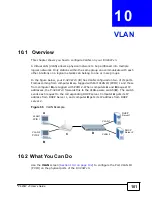
Chapter 10 VLAN
P-320W v3 User’s Guide
102
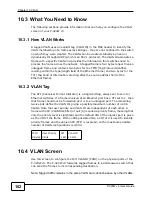
10.3 What You Need to Know
The following sections provide information that can help you configure the VLAN
screen of your P-320W v3.
10.3.1 How VLAN Works
A tagged VLAN uses an explicit tag (VLAN ID) in the MAC header to identify the
VLAN membership of a frame across bridges - they are not confined to the switch
on which they were created. The VLANs can be created statically by hand or
dynamically through GVRP (which is an 802.1 protocol). The VLAN ID associates a
frame with a specific VLAN and provides the information that switches need to
process the frame across the network. A tagged frame is four bytes longer than an
untagged frame and contains two bytes for the TPID (Tag Protocol Identifier,
residing within the type/length field of the Ethernet frame) and two bytes for the
TCI (Tag Control Information, starting after the source address field of the
Ethernet frame).
10.3.2 VLAN Tag
The CFI (Canonical Format Indicator) is a single-bit flag, always set to zero for
Ethernet switches. If a frame received at an Ethernet port has a CFI set to 1, then
that frame should not be forwarded as it is to an untagged port. The remaining
twelve bits define the VLAN ID, giving a possible maximum number of 4,096
VLANs. Note that user priority and VLAN ID are independent of each other. A
frame with VID (VLAN Identifier) of null (0) is called a priority frame, meaning that
only the priority level is significant and the default VID of the ingress port is given
as the VID of the frame. Of the 4096 possible VIDs, a VID of 0 is used to identify
priority frames and the value 4095 (FFF) is reserved, so the maximum possible
number of VLAN configurations is 4,094.
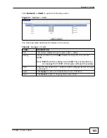
10.4 VLAN Screen
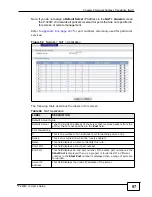
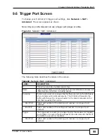
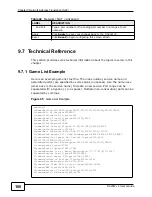
Use this screen to configure the Port VLAN ID (PVID) on the physical ports of the
P-320W v3. The P-320W v3 forwards tagged frames to a VLAN-aware switch that
can send the frames to its corresponding destination.
Note: Tagged traffic remains in the same VLAN and cannot be seen by other VLANs.
TPID
2 Bytes
User Priority
3 Bits
CFI
1 Bit
VLAN ID
12 bits
Summary of Contents for P-320W v3
Page 2: ......
Page 8: ...Safety Warnings P 320W v3 User s Guide 8 ...
Page 10: ...Contents Overview P 320W v3 User s Guide 10 ...
Page 18: ...Table of Contents P 320W v3 User s Guide 18 ...
Page 20: ...20 ...
Page 24: ...Chapter 1 Getting to Know Your P 320W v3 P 320W v3 User s Guide 24 ...
Page 36: ...Chapter 2 Introducing the Web Configurator P 320W v3 User s Guide 36 ...
Page 54: ...54 ...
Page 72: ...Chapter 4 Wireless LAN P 320W v3 User s Guide 72 ...
Page 76: ...Chapter 5 Wireless Client Mode P 320W v3 User s Guide 76 ...
Page 88: ...Chapter 7 LAN P 320W v3 User s Guide 88 ...
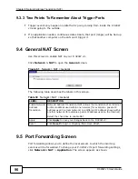
Page 104: ...Chapter 10 VLAN P 320W v3 User s Guide 104 ...
Page 105: ...105 PART III Security Firewall 117 Content Filtering 125 ...
Page 106: ...106 ...
Page 116: ...Chapter 11 WAN P 320W v3 User s Guide 116 ...
Page 124: ...Chapter 12 Firewall P 320W v3 User s Guide 124 ...
Page 130: ...130 ...
Page 134: ...Chapter 14 Static Route P 320W v3 User s Guide 134 ...
Page 140: ...Chapter 15 Remote Management P 320W v3 User s Guide 140 ...
Page 154: ...Chapter 16 Universal Plug and Play UPnP P 320W v3 User s Guide 154 ...
Page 155: ...155 PART V Maintenance and Troubleshooting System 157 Logs 163 Product Specifications 193 ...
Page 156: ...156 ...
Page 178: ...Chapter 18 Logs P 320W v3 User s Guide 178 ...
Page 184: ...Chapter 19 Tools P 320W v3 User s Guide 184 ...
Page 192: ...Chapter 20 Troubleshooting P 320W v3 User s Guide 192 ...
Page 196: ...Chapter 21 Product Specifications P 320W v3 User s Guide 196 ...
Page 198: ...198 ...
Page 260: ...Index P 320W v3 User s Guide 260 ...
Page 261: ......
Page 262: ......


