


Chapter 3 Hardware Overview
MGS-3712/MGS-3012F User’s Guide
45
3.1.6 ALARM Slot
The
ALARM
slot (fitted with the alarm connector) allows you to connect devices to the
Switch, such as smoke or movement detectors, sensors, or even other ZyXEL switches which
support the external alarm feature. This feature is in addition to the system alarm, which
detects abnormal temperatures, voltage levels and fan speeds on the Switch.
Your Switch can respond to an external alarm in five ways.
• The
ALM
LED shows an alert.
• The
ALARM
slot can send an external alarm on to another device such as an alarm bell.
• By daisy-chaining the alarm sensor cables from one Switch to another ZyXEL switch
which supports this feature, the external alarm alert (but not the system alarm) is received
on each Switch.
• The Switch can also be configured to send an SNMP trap to the SNMP server. See
for more information on using SNMP.
• The Switch can be configured to create an error log of the alarm. See
for more information on using the system log.
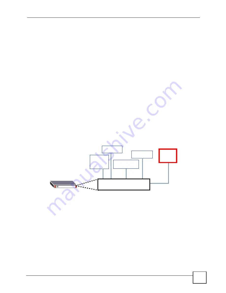
3.1.6.1 Connect a Sensor to the ALARM Slot
This section shows you how to connect up to four sensors to the
ALARM
slot and to let a bell
signal the alarm, as shown in the diagram below.
Figure 19
Connecting Sensors to the
ALARM
connector
Follow these steps to connect an external sensor device to the Switch.
1
Use a connector to connect wires of the correct gauge to the sensor’s power output pins.
See
for the wire specifications. Check the sensor’s
documentation to identify its two power output pins.
2
Connect these two wires to any one of the following pairs of power input pins on the
Switch’s
ALARM
connector - (4,5) (6,7) (8,9) (10,11). The pin numbers run from the
right side of the connector to the left.
2a
Connect each of the sensor’s two power output wires to the
ALARM
connector by
depressing the spring clip corresponding to the pin you are connecting to.
2b
Insert the wire and release the spring clip.
Alarm
bell
Forced
Smoke
Movement
Flooding
ALARM Slot
Entry
Summary of Contents for MGS-3712
Page 2: ......
Page 7: ...Safety Warnings MGS 3712 MGS 3012F User s Guide 7 ...
Page 8: ...Safety Warnings MGS 3712 MGS 3012F User s Guide 8 ...
Page 20: ...Table of Contents MGS 3712 MGS 3012F User s Guide 20 ...
Page 28: ...List of Tables MGS 3712 MGS 3012F User s Guide 28 ...
Page 30: ...30 ...
Page 38: ...Chapter 2 Hardware Installation and Connection MGS 3712 MGS 3012F User s Guide 38 ...
Page 50: ...50 ...
Page 70: ...Chapter 6 System Status and Port Statistics MGS 3712 MGS 3012F User s Guide 70 ...
Page 82: ...Chapter 7 Basic Setting MGS 3712 MGS 3012F User s Guide 82 ...
Page 84: ...84 ...
Page 132: ...Chapter 15 Link Aggregation MGS 3712 MGS 3012F User s Guide 132 ...
Page 142: ...Chapter 17 Port Security MGS 3712 MGS 3012F User s Guide 142 ...
Page 148: ...Chapter 18 Classifier MGS 3712 MGS 3012F User s Guide 148 Figure 80 Classifier Example ...
Page 153: ...Chapter 19 Policy Rule MGS 3712 MGS 3012F User s Guide 153 Figure 83 Policy Example ...
Page 154: ...Chapter 19 Policy Rule MGS 3712 MGS 3012F User s Guide 154 ...
Page 170: ...Chapter 21 Multicast MGS 3712 MGS 3012F User s Guide 170 ...
Page 184: ...Chapter 22 Authentication Accounting MGS 3712 MGS 3012F User s Guide 184 ...
Page 214: ...Chapter 25 Two Rate Three Color Marker MGS 3712 MGS 3012F User s Guide 214 ...
Page 215: ...215 PART IV IP Application Static Route 217 DHCP 221 ...
Page 216: ...216 ...
Page 220: ...Chapter 26 Static Route MGS 3712 MGS 3012F User s Guide 220 ...
Page 228: ...Chapter 27 DHCP MGS 3712 MGS 3012F User s Guide 228 ...
Page 230: ...230 ...
Page 256: ...Chapter 30 Diagnostic MGS 3712 MGS 3012F User s Guide 256 ...
Page 260: ...Chapter 31 Syslog MGS 3712 MGS 3012F User s Guide 260 ...
Page 274: ...274 ...
Page 278: ...Chapter 36 Troubleshooting MGS 3712 MGS 3012F User s Guide 278 ...
Page 286: ...286 ...
Page 290: ...Appendix A Common Services MGS 3712 MGS 3012F User s Guide 290 ...
Page 294: ...Appendix B Legal Information MGS 3712 MGS 3012F User s Guide 294 ...


