Chapter 3 Hardware Panels
XMG1930 Series User’s Guide
38
5
Insert the dust plug into the ports on the transceiver and the cables.
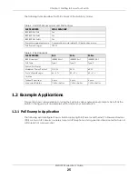
Figure 16
Removing the Fiber Optic Cables
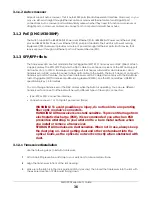
Figure 17
Opening the Transceiver’s Latch Example
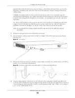
Figure 18
Transceiver Removal Example
3.1.4 USB Port
With instructions from customer support, this USB Type C connector is for troubleshooting only.
3.2 Rear Panel
The following figures show the rear panels of the Switch. The rear panels contain:
Figure 19
Rear Panel: XMG1930-30
Figure 20
Rear Panel: XMG1930-30HP
3.2.1 Grounding
Grounding is a safety measure to direct excess electric charge to the ground. It prevents damage to
the Switch, and protects you from electrocution. Use the grounding screw on the rear panel and the
ground wire of the AC power supply to ground the Switch.


