background image

 Chapter 18 Syslog

ES-315/ES-315-F User’s Guide

117

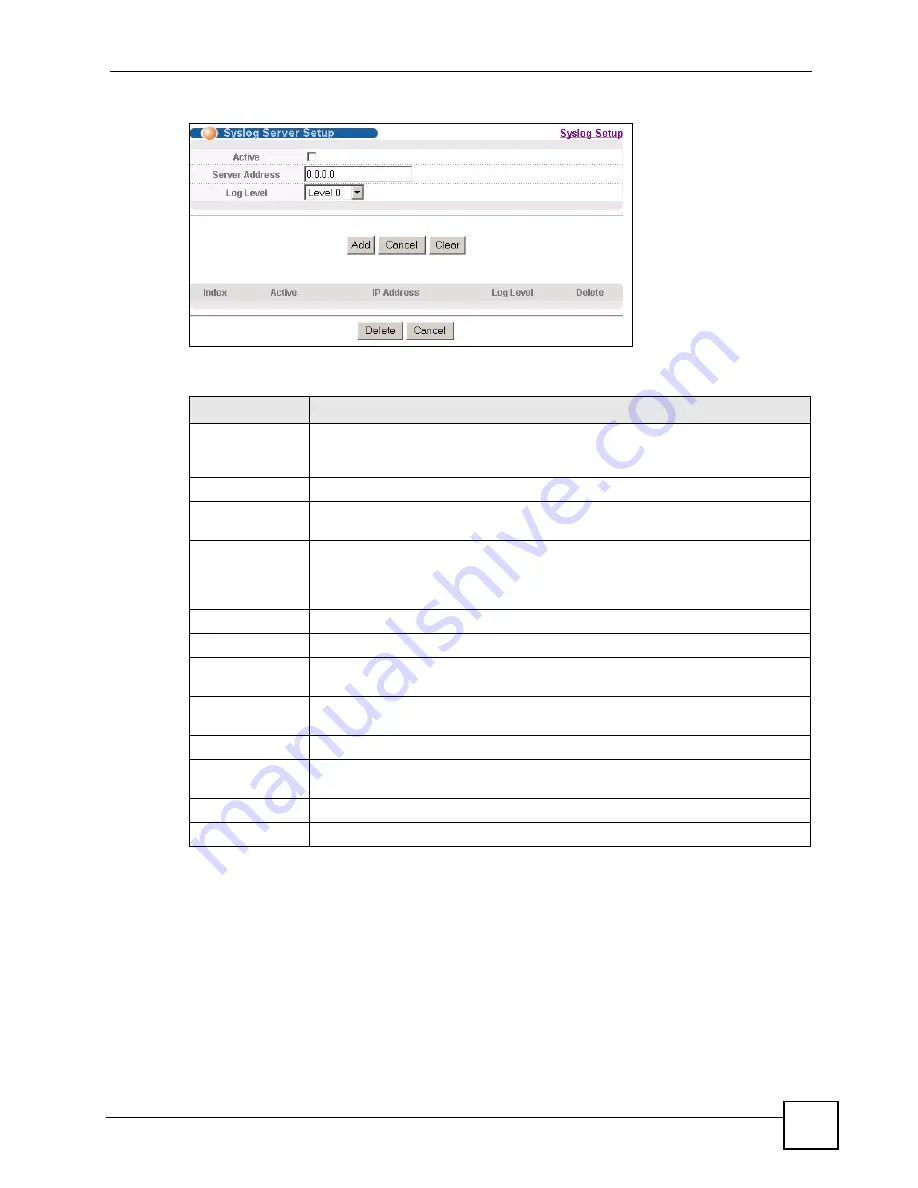
Figure 66   

Syslog: Server Setup 

The following table describes the labels in this screen.

Table 43   

Syslog: Server Setup 

LABEL

DESCRIPTION

Active

Select this check box to have the device send logs to this syslog server. Clear the 

check box if you want to create a syslog server entry but not have the device send 

logs to it (you can edit the entry later).

Server Address

Enter the IP address of the syslog server.

Log Level 

Select the severity level(s) of the logs that you want the device to send to this 

syslog server. The lower the number, the more critical the logs are.

Add

Click 

Add

 to save your changes to the Switch’s run-time memory. The Switch 

loses these changes if it is turned off or loses power, so use the 

Save

 link on the 

top navigation panel to save your changes to the non-volatile memory when you 

are done configuring.

Cancel

Click 

Cancel

 to begin configuring this screen afresh.

Clear

Click 

Clear


to return the fields to the factory defaults.

Index

This is the index number of a syslog server entry. Click this number to edit the 

entry.

Active

This field displays 

Yes


if the device is to send logs to the syslog server. 

No


displays if the device is not to send logs to the syslog server.

IP Address

This field displays the IP address of the syslog server.

Log Level

This field displays the severity level of the logs that the device is to send to this 

syslog server.

Delete

Select an entry’s 

Delete


check box and click 

Delete


to remove the entry.

Cancel

Click 

Cancel

 to begin configuring this screen afresh.

Summary of Contents for ES-315

Page 1: ...www zyxel com ES 315 ES 315 F Intelligent Layer 2 Managed Switch User s Guide Version 3 70 8 2007 Edition 1 DEFAULT LOGIN IP Address http 192 168 1 1 User Name admin Password 1234 ...

Page 2: ......

Page 3: ...access Web Configurator Online Help Embedded web help for descriptions of individual screens and supplementary information It is recommended you use the web configurator to configure the Switch Supporting Disk Refer to the included CD for support documents ZyXEL Web Site Please refer to www zyxel com for additional support documentation and product certifications User Guide Feedback Help us help y...

Page 4: ...ont A key stroke is denoted by square brackets and uppercase text for example ENTER means the enter or return key on your keyboard Enter means for you to type one or more characters and then press the ENTER key Select or choose means for you to use one of the predefined choices A right angle bracket within a screen name denotes a mouse click For example Maintenance Log Log Setting means you first ...

Page 5: ...ser s Guide 5 Icons Used in Figures Figures in this User s Guide may use the following generic icons The Switch icon is not an exact representation of your device The Switch Computer Notebook computer Server DSLAM Firewall Telephone Router ...

Page 6: ... on the power adaptor or cord and do NOT place the product where anyone can walk on the power adaptor or cord Do NOT use the device if the power adaptor or cord is damaged as it might cause electrocution If the power adaptor or cord is damaged remove it from the device and the power source Do NOT attempt to repair the power adaptor or cord Contact your local vendor to order a new one Do not use th...

Page 7: ...Safety Warnings ES 315 ES 315 F User s Guide 7 ...

Page 8: ...Safety Warnings ES 315 ES 315 F User s Guide 8 ...

Page 9: ... and Port Statistics 43 Basic Setting 47 Advanced 55 VLAN 57 Static MAC Forward Setup 63 Filtering 65 Broadcast Storm Control 67 Bandwidth Control 69 Queuing Method 71 Multicast 73 IP Application 85 Static Route 87 Management 91 Maintenance 93 Access Control 99 Diagnostic 113 Syslog 115 MAC Table 119 ARP Table 121 Troubleshooting and Product Specifications 125 Troubleshooting 127 Product Specifica...

Page 10: ...Contents Overview ES 315 ES 315 F User s Guide 10 ...

Page 11: ...rdware 21 Chapter 1 Getting to Know Your Switch 23 1 1 Introduction 23 1 1 1 Overview 23 1 1 2 IEEE 802 1Q VLAN Application Example 23 1 2 Ways to Manage the Switch 24 1 3 Good Habits for Managing the Switch 24 Chapter 2 Hardware Overview 27 2 1 LEDs 27 2 2 Rear and Base Panels 28 Part II Basic Configuration 31 Chapter 3 The Web Configurator 33 3 1 Introduction 33 3 2 System Login 33 3 3 The Statu...

Page 12: ...tistics 43 5 1 Overview 43 5 2 Port Status Summary 43 5 2 1 Status Port Details 44 Chapter 6 Basic Setting 47 6 1 Overview 47 6 2 System Information 47 6 3 General Setup 48 6 4 Introduction to VLANs 49 6 5 Switch Setup Screen 49 6 6 IP Setup 51 6 6 1 Management IP Addresses 51 6 7 Port Setup 53 Part III Advanced 55 Chapter 7 VLAN 57 7 1 Introduction to IEEE 802 1Q Tagged VLANs 57 7 1 1 Forwarding ...

Page 13: ...up 69 Chapter 12 Queuing Method 71 12 1 Queuing Method Overview 71 12 1 1 Strictly Priority Queuing 71 12 1 2 Weighted Fair Queuing 71 12 2 Configuring Queuing 72 Chapter 13 Multicast 73 13 1 Multicast Overview 73 13 1 1 IP Multicast Addresses 73 13 1 2 IGMP Filtering 73 13 1 3 IGMP Snooping 73 13 2 Multicast Status 74 13 3 Multicast Setting 74 13 4 IGMP Filtering Profile 76 13 5 MVR Overview 77 1...

Page 14: ...d Line 96 15 8 1 Filename Conventions 97 15 8 2 FTP Command Line Procedure 97 15 8 3 GUI based FTP Clients 98 15 8 4 FTP Restrictions 98 Chapter 16 Access Control 99 16 1 Access Control Overview 99 16 2 The Access Control Main Screen 99 16 3 About SNMP 100 16 3 1 Supported MIBs 101 16 3 2 SNMP Traps 101 16 3 3 Configuring SNMP 103 16 3 4 Setting Up Login Accounts 104 16 4 SSH Overview 105 16 5 How...

Page 15: ... MAC Table Overview 119 19 2 Viewing the MAC Table 120 Chapter 20 ARP Table 121 20 1 ARP Table Overview 121 20 1 1 How ARP Works 121 20 2 Viewing the ARP Table 121 Part VI Troubleshooting and Product Specifications 125 Chapter 21 Troubleshooting 127 21 1 Power Hardware Connections and LEDs 127 21 2 Switch Access and Login 128 Chapter 22 Product Specifications 131 22 1 General Switch Specifications...

Page 16: ...Table of Contents ES 315 ES 315 F User s Guide 16 Appendix B Common Services 149 Appendix C Legal Information 153 Appendix D Customer Support 157 Index 163 ...

Page 17: ...tch Setup 50 Figure 20 Basic Setting IP Setup 51 Figure 21 Basic Setting Port Setup 53 Figure 22 Advanced Application VLAN VLAN Status 58 Figure 23 Advanced Application VLAN VLAN Detail 59 Figure 24 Advanced Application VLAN Static VLAN 60 Figure 25 Advanced Application VLAN VLAN Port Setting 61 Figure 26 Advanced Application Static MAC Forwarding 63 Figure 27 Advanced Application Filtering 65 Fig...

Page 18: ...TTPS Implementation 107 Figure 58 Security Alert Dialog Box Internet Explorer 108 Figure 59 Security Certificate 1 Netscape 108 Figure 60 Security Certificate 2 Netscape 109 Figure 61 Example Lock Denoting a Secure Connection 109 Figure 62 Access Control Service Access Control 110 Figure 63 Access Control Remote Management 111 Figure 64 Diagnostic 113 Figure 65 Syslog 116 Figure 66 Syslog Server S...

Page 19: ...Advanced Application FIltering 65 Table 18 Advanced Application Broadcast Storm Control 67 Table 19 Advanced Application Bandwidth Control 69 Table 20 Queuing Method 72 Table 21 Multicast Status 74 Table 22 Advanced Application Multicast Multicast Setting 75 Table 23 Advanced Application Multicast Multicast Setting IGMP Filtering Profile 77 Table 24 Advanced Application Multicast Multicast Setting...

Page 20: ...e Specifications 131 Table 48 Feature Specifications 132 Table 49 Standards Supported 133 Table 50 IP Address Network Number and Host ID Example 140 Table 51 Subnet Masks 141 Table 52 Maximum Host Numbers 141 Table 53 Alternative Subnet Mask Notation 141 Table 54 Subnet 1 143 Table 55 Subnet 2 144 Table 56 Subnet 3 144 Table 57 Subnet 4 144 Table 58 Eight Subnets 144 Table 59 24 bit Network Number...

Page 21: ...21 PART I Introduction and Hardware Getting to Know Your Switch 23 Hardware Overview 27 ...

Page 22: ...22 ...

Page 23: ...p to four devices to your network The following figure shows the Switch A connecting several devices 1 4 and allowing them to communicate with one another and access the Internet through the Internet Service Provider s network switch B Figure 1 Internet Access through the Switch 1 1 2 IEEE 802 1Q VLAN Application Example A VLAN Virtual Local Area Network allows a physical network to be partitioned...

Page 24: ...owing methods to manage the Switch Web Configurator This is recommended for everyday management of the Switch using a supported web browser See Chapter 3 on page 33 Command Line Interface Line commands offer an alternative to the web configurator and in some cases are necessary to configure advanced features See the Command Reference Guide FTP Use FTP for firmware upgrades and configuration backup...

Page 25: ...oring an earlier working configuration may be useful if the device becomes unstable or even crashes If you forget your password you will have to reset the Switch to its factory default settings If you backed up an earlier configuration file you would not have to totally re configure the Switch You could simply restore your last configuration ...

Page 26: ...Chapter 1 Getting to Know Your Switch ES 315 ES 315 F User s Guide 26 ...

Page 27: ...ection describes the front and rear panels of the switch See your Quick Start Guide for information on making hardware connections 2 1 LEDs The following figures show the front panels of the ES 315 and ES 315 F Figure 3 Front Panel ES 315 Figure 4 Front Panel ES 315 F ...

Page 28: ... receiving power Off The Switch is not receiving power ALM On Red The Switch is malfunctioning Off The Switch is functioning normally or is not receiving power LAN1 LAN4 On Steady The Switch has a successful Ethernet connection on the respective LAN port Blinking The Switch is sending or receiving data on the respective LAN port Off There is no device connected to the respective LAN port WAN On St...

Page 29: ...Chapter 2 Hardware Overview ES 315 ES 315 F User s Guide 29 Figure 7 Base Panel ES 315 F POWER ...

Page 30: ...Chapter 2 Hardware Overview ES 315 ES 315 F User s Guide 30 ...

Page 31: ...31 PART II Basic Configuration The Web Configurator 33 Initial Setup Example 39 System Status and Port Statistics 43 Basic Setting 47 ...

Page 32: ...32 ...

Page 33: ...use the web configurator you need to allow Web browser pop up windows from your device Web pop up blocking is enabled by default in Windows XP SP Service Pack 2 JavaScript enabled by default Java permissions enabled by default 3 2 System Login 1 Start your web browser 2 Type http and the IP address of the Switch for example the default is 192 168 1 1 in the Location or Address field Press ENTER 3 ...

Page 34: ...e Screen Status A Click the menu items to open submenu links and then click on a submenu link to open the screen in the main window B C D E These are quick links which allow you to perform certain tasks no matter which screen you are currently working in B Click this link to save your configuration into the Switch s nonvolatile memory Nonvolatile memory is the configuration of your Switch that sta...

Page 35: ...ON MANAGEMENT System Info General Setup Switch Setup IP Setup Port Setup VLAN VLAN Port Setting Static VLAN Static MAC Forwarding Filtering Bandwidth Control Broadcast Storm Control Queuing Method Multicast Multicast Setting IGMP Filtering Profile MVR Group Configuration Static Routing Maintenance Firmware Upgrade Restore Configuration Backup Configuration Load Factory Default Save Configuration R...

Page 36: ...ndwidth allowed from specified source s to specified destination s Queuing Method This link takes you to a screen where you can configure queuing with associated queue weights for each port Multicast This link takes you to screens where you can configure various multicast features and create multicast VLANs IP Application Static Routing This link takes you to a screen where you can configure stati...

Page 37: ...ve your configuration to nonvolatile memory Nonvolatile memory refers to the Switch s storage that remains even if the Switch s power is turned off Use the Save link when you are done with a configuration session 3 5 Switch Lockout You could block yourself and all others from managing the Switch if you do one of the following 1 Delete the management VLAN default is VLAN 1 2 Filter all traffic to t...

Page 38: ...e Switch for three to five seconds then release it The Switch restarts All information is reset to defaults including the IP address 192 168 1 1 the username admin and the password 1234 3 7 Logging Out of the Web Configurator Click Logout in a screen to exit the web configurator You have to log in with your password again after you log out This is recommended after you finish a management session ...

Page 39: ...ion steps for the initial setup Create a VLAN Set port VLAN ID Configure the switch IP management address 4 1 1 Creating a VLAN VLANs confine broadcast frames to the VLAN group in which the port s belongs You can do this with tagged static VLAN with fixed port members In this example you want to configure port 1 as a member of VLAN 2 Figure 12 Initial Setup Network Example VLAN ...

Page 40: ...lect Fixed to configure port 1 to be a permanent member of the VLAN only 4 To ensure that VLAN unaware devices such as computers and hubs can receive frames properly clear the TX Tagging check box to set the switch to remove VLAN tags before sending 5 Click Add to save the settings to the run time memory Settings in the run time memory are lost when the Switch s power is turned off 4 1 2 Setting P...

Page 41: ...the run time memory Settings in the run time memory are lost when the Switch s power is turned off 4 2 Configuring Switch Management IP Address The default management IP address of the switch is 192 168 1 1 You can configure another IP address in a different subnet for management purposes The following figure shows an example Figure 14 Initial Setup Example Management IP Address 1 Connect your com...

Page 42: ... 4 Configure the fields in the Management IP Addresses section For the VLAN2 network enter 192 168 2 1 as the IP address and 255 255 255 0 as the subnet mask In the VID field enter the ID of the VLAN group to which you want this management IP address to belong 2 in this example This is the same as the VLAN ID you configure in the Static VLAN screen 5 Click Add to save your changes back to the run ...

Page 43: ... statistics click Status in all web configurator screens to display the Status screen as shown next Figure 15 Status The following table describes the labels in this screen Table 5 Status LABEL DESCRIPTION Port This identifies the Ethernet port Click a port number to display the Port Details screen refer to Figure 16 on page 44 Name This is the name you assigned to this port in the Basic Setting P...

Page 44: ... transmitted frames on this port RxPkts This field shows the number of received frames on this port Errors This field shows the number of received errors on this port Tx KB s This field shows the number of kilobytes per second transmitted on this port Rx KB s This field shows the number of kilobytes per second received on this port Up Time This field shows the total amount of time in hours minutes...

Page 45: ...ws the number of good multicast packets transmitted Broadcast This field shows the number of good broadcast packets transmitted Pause This field shows the number of 802 3x Pause packets transmitted Rx Packet The following fields display detailed information about packets received RX Packet This field shows the number of good packets unicast multicast and broadcast received Multicast This field sho...

Page 46: ...t were between 65 and 127 octets in length 128 255 This field shows the number of packets including bad packets received that were between 128 and 255 octets in length 256 511 This field shows the number of packets including bad packets received that were between 256 and 511 octets in length 512 1023 This field shows the number of packets including bad packets received that were between 512 and 10...

Page 47: ...lobal Switch features The IP Setup screen allows you to configure a Switch IP address in each routing domain subnet mask s and DNS domain name server for management purposes The Port Setup screen allows you to configure Switch port settings 6 2 System Information In the navigation panel click Basic Setting and System Info to display the screen as shown You can check the firmware version number in ...

Page 48: ...e to use trial and error to find a protocol that works The main differences between them are the time format When you select the Daytime RFC 867 format the Switch displays the day month year and time with no time zone adjustment When you use this format it is recommended that you use a Daytime timeserver within your geographical time zone Time RFC 868 format displays a 4 byte integer giving the to...

Page 49: ...o each and every individual port With VLAN all broadcasts are confined to a specific broadcast domain VLAN is unidirectional it only governs outgoing traffic See Chapter 7 on page 57 for information on 802 1Q tagged VLANs 6 5 Switch Setup Screen Click Basic Setting and then Switch Setup in the navigation panel to display the screen as shown This screen allows you to set priority levels on the Swit...

Page 50: ...p Level 7 Typically used for network control traffic such as router configuration messages Level 6 Typically used for voice traffic that is especially sensitive to jitter jitter is variation in delay Level 5 Typically used for video that consumes high bandwidth and is sensitive to jitter Level 4 Typically used for controlled load latency sensitive traffic such as SNA Systems Network Architecture t...

Page 51: ... Management IP Addresses The switch needs an IP address for it to be managed over the network The factory default IP address is 192 168 1 1 The subnet mask specifies the network number portion of an IP address The factory default subnet mask is 255 255 255 0 You can configure up to 5 IP addresses which are used to access and manage the switch from the ports belonging to the pre defined VLAN s 4 st...

Page 52: ...nnot access the device To access the switch make sure the port that you are connected to is a member of Management VLAN Apply Click Apply to save your changes to the switch s run time memory The switch loses these changes if it is turned off or loses power so use the Save link on the top navigation panel to save your changes to the non volatile memory when you are done configuring Cancel Click Can...

Page 53: ... Setting Port Setup LABEL DESCRIPTION Port This is the port index number Settings in this row apply to all ports Use this row only if you want to make some settings the same for all ports Use this row first to set the common settings and then make adjustments on a port by port basis Note Changes in this row are copied to all the ports as soon as you make them Active Select this check box to enable...

Page 54: ...ausing packet discards and frame losses Flow Control is used to regulate transmission of signals to match the bandwidth of the receiving port The Switch uses IEEE802 3x flow control in full duplex mode and backpressure flow control in half duplex mode IEEE802 3x flow control is used in full duplex mode to send a pause signal to the sending port causing it to temporarily stop sending signals when t...

Page 55: ...55 PART III Advanced VLAN 57 Static MAC Forward Setup 63 Filtering 65 Bandwidth Control 69 Broadcast Storm Control 67 Queuing Method 71 Multicast 73 ...

Page 56: ...56 ...

Page 57: ...LANs Note that user priority and VLAN ID are independent of each other A frame with VID VLAN Identifier of null 0 is called a priority frame meaning that only the priority level is significant and the default VID of the ingress port is given as the VID of the frame Of the 4096 possible VIDs a VID of 0 is used to identify priority frames and value 4095 FFF is reserved so the maximum possible VLAN c...

Page 58: ...his screen to view detailed port settings and status of the VLAN group See Section 7 1 on page 57 for more information on static VLAN Click on an index number in the VLAN Status screen to display VLAN details Table 12 Advanced Application VLAN VLAN Status LABEL DESCRIPTION The Number of VLAN This is the number of VLANs configured on the Switch Index This is the VLAN index number Click on an index ...

Page 59: ...ion VLAN VLAN Detail LABEL DESCRIPTION VLAN Status Click this to go to the VLAN Status screen VID This is the VLAN identification number that was configured in the Static VLAN screen Port Number This column displays the ports that are participating in a VLAN A tagged port is marked as T an untagged port is marked as U and ports not participating in a VLAN are marked as Elapsed Time This field show...

Page 60: ... port basis Note Changes in this row are copied to all the ports as soon as you make them Control Select Normal for the port to not be part of the VLAN group This is the default selection On GVRP capable devices the Normal status allows the port to join the VLAN dynamically However the Switch does not support GVRP Select Fixed for the port to be a permanent member of this VLAN group Select Forbidd...

Page 61: ... Delete Click Delete to remove the selected entry from the summary table Cancel Click Cancel to clear the Delete check boxes Table 14 Advanced Application VLAN Static VLAN continued LABEL DESCRIPTION Table 15 Advanced Application VLAN VLAN Port Setting LABEL DESCRIPTION Port This field displays the port number Settings in this row apply to all ports Use this row only if you want to make some setti...

Page 62: ...ll untagged frames will be dropped Select Untag Only to accept only untagged frames on this port All tagged frames will be dropped Apply Click Apply to save your changes to the Switch s run time memory The Switch loses these changes if it is turned off or loses power so use the Save link on the top navigation panel to save your changes to the non volatile memory when you are done configuring Cance...

Page 63: ... address rules you are setting static MAC addresses for a port This may reduce the need for broadcasting Click Advanced Applications Static MAC Forwarding in the navigation panel to display the configuration screen as shown Figure 26 Advanced Application Static MAC Forwarding The following table describes the labels in this screen Table 16 Advanced Application Static MAC Forwarding LABEL DESCRIPTI...

Page 64: ...ear to begin configuring this screen afresh Index Click an index number to modify a static MAC address rule for a port Active This field displays whether this static MAC address forwarding rule is active Yes or not No You may temporarily deactivate a rule without deleting it Name This field displays the descriptive name for identification purposes for this static MAC address forwarding rule MAC Ad...

Page 65: ...The following table describes the related labels in this screen Table 17 Advanced Application FIltering LABEL DESCRIPTION Active Make sure you select this check box to activate your rule You may temporarily deactivate a rule without deleting it by deselecting this check box Name Type a descriptive name up to 32 printable ASCII characters for this rule This is for identification only MAC Type a MAC...

Page 66: ...r of the rule Click an index number to change the settings Active This field displays Yes when the rule is activated and No when is it deactivated Name This field displays the descriptive name for this rule This is for identification purpose only MAC Address This field displays the source destination MAC address with the VLAN identification number to which the MAC address belongs VID This field di...

Page 67: ...n your network Click Advanced Application Broadcast Storm Control in the navigation panel to display the screen as shown next Figure 28 Advanced Application Broadcast Storm Control The following table describes the labels in this screen Table 18 Advanced Application Broadcast Storm Control LABEL DESCRIPTION Active Select this check box to enable traffic storm control on the Switch Clear this check...

Page 68: ... time memory The Switch loses these changes if it is turned off or loses power so use the Save link on the top navigation panel to save your changes to the non volatile memory when you are done configuring Cancel Click Cancel to reset the fields Table 18 Advanced Application Broadcast Storm Control continued LABEL DESCRIPTION ...

Page 69: ...and or out going traffic flows on a port 11 2 Bandwidth Control Setup Click Advanced Application Bandwidth Control in the navigation panel to bring up the screen as shown next Figure 29 Advanced Application Bandwidth Control The following table describes the related labels in this screen Table 19 Advanced Application Bandwidth Control LABEL DESCRIPTION Active Select this check box to enable bandwi...

Page 70: ... bandwidth allowed in kilobits per second Kbps for the incoming traffic flow on a port Active Select this check box to activate egress rate limits on this port Egress Rate Specify the maximum bandwidth allowed in kilobits per second Kbps for the out going traffic flow on a port Apply Click Apply to save your changes to the Switch s run time memory The Switch loses these changes if it is turned off...

Page 71: ...irst When that queue empties traffic on the next highest priority queue Q2 is transmitted until Q2 empties and then traffic is transmitted on Q1 and so on If higher priority queues never empty then traffic on lower priority queues never gets sent SP does not automatically adapt to changing network requirements 12 1 2 Weighted Fair Queuing Weighted Fair Queuing is used to guarantee each queue s min...

Page 72: ...st Weighted Fair Queuing is used to guarantee each queue s minimum bandwidth based on their bandwidth portion weight the number you configure in the Weight field Queues with larger weights get more guaranteed bandwidth than queues with smaller weights Q0 Q3 Weight When you select WFQ enter the queue weight here Bandwidth is divided across the different traffic queues according to their weights Que...

Page 73: ...ces IP addresses in the Class D range 224 0 0 0 to 239 255 255 255 are used for IP multicasting Certain IP multicast numbers are reserved by IANA for special purposes see the IANA web site for more information 13 1 2 IGMP Filtering With the IGMP filtering feature you can control which IGMP groups a subscriber on a port can join This allows you to control the distribution of multicast services such...

Page 74: ...he multicast group information See Section 13 1 on page 73 for more information on multicasting Figure 31 Advanced Application Multicast The following table describes the labels in this screen 13 3 Multicast Setting Click Advanced Applications Multicast Multicast Setting link to display the screen as shown See Section 13 1 on page 73 for more information on multicasting Table 21 Multicast Status L...

Page 75: ...any seconds the Switch waits for an IGMP report before removing an IGMP snooping membership entry when an IGMP leave message is received from a host 802 1p Priority Select a priority level 0 7 to which the Switch changes the priority in outgoing IGMP control packets Otherwise select No Change to not replace the priority IGMP Filtering Select Active to enable IGMP filtering to control which IGMP gr...

Page 76: ...ame s is dropped on this port IGMP Filtering Profile Select the name of the IGMP filtering profile to use for this port Otherwise select Default to prohibit the port from joining any multicast group You can create IGMP filtering profiles in the Multicast Multicast Setting IGMP Filtering Profile screen IGMP Querier Mode The Switch treats an IGMP query port as being connected to an IGMP multicast ro...

Page 77: ...dress for a range of IP addresses that you want to belong to the IGMP filter profile If you want to add a single multicast IP address enter it in both the Start Address and End Address fields Add Click Add to save the profile to the Switch s run time memory The Switch loses these changes if it is turned off or loses power so use the Save link on the top navigation panel to save your changes to the...

Page 78: ...n the Switch that can send and receive multicast traffic in a multicast VLAN while a receiver port can only receive multicast traffic Once configured the Switch maintains a forwarding table that matches the multicast stream to the associated multicast group 13 5 2 MVR Modes You can set your Switch to operate in either dynamic or compatible mode In dynamic mode the Switch sends IGMP leave and join ...

Page 79: ... to VLAN 1 on the receiver port in this case a DSL port on the Switch If there is another subscriber device connected to this port in the same subscriber VLAN the receiving port will still be on the list of forwarding destination for the multicast traffic Otherwise the Switch removes the receiver port from the forwarding table Figure 35 MVR Multicast Television Example 13 6 General MVR Configurati...

Page 80: ...ackets belonging to this multicast VLAN Mode Specify the MVR mode on the Switch Choices are Dynamic and Compatible Select Dynamic to send IGMP reports to all MVR source ports in the multicast VLAN Select Compatible to set the Switch not to send IGMP reports Port This field displays the port number on the Switch Settings in this row apply to all ports Use this row only if you want to make some sett...

Page 81: ...The Switch loses these changes if it is turned off or loses power so use the Save link on the top navigation panel to save your changes to the non volatile memory when you are done configuring Cancel Click Cancel to begin configuring this screen afresh VLAN This field displays the multicast VLAN ID Active This field displays whether the multicast group is enabled or not Name This field displays th...

Page 82: ...ast group in dotted decimal notation Refer to Section 13 1 1 on page 73 for more information on IP multicast addresses End Address Enter the ending IP multicast address of the multicast group in dotted decimal notation Enter the same IP address as the Start Address field if you want to configure only one IP address for a multicast group Refer to Section 13 1 1 on page 73 for more information on IP...

Page 83: ...e Switch to forward the multicast group traffic to the subscribers configure multicast group settings in the Group Configuration screen The following figure shows an example where two multicast groups News and Movie are configured for the multicast VLAN 200 Figure 40 MVR Group Configuration Example ...

Page 84: ...Chapter 13 Multicast ES 315 ES 315 F User s Guide 84 Figure 41 MVR Group Configuration Example ...

Page 85: ...85 PART IV IP Application Static Route 87 ...

Page 86: ...86 ...

Page 87: ... telnet SSH or SNMP The Switch can communicate with the management stations on the networks behind the default gateway The figure below shows a Telnet session in network N1 behind the default gateway R1 Static routes are used to tell the Switch how to communicate with management stations not reachable via the default gateway The figure below shows an SNMP manager behind router R2 in network N2 A s...

Page 88: ...he cost of transmission for routing purposes IP routing uses hop count as the measurement of cost with a minimum of 1 for directly connected networks Enter a number that approximates the cost for this link The number need not be precise but it must be between 1 and 15 In practice 2 or 3 is usually a good number Add Click Add to insert a new static route to the Switch s run time memory The Switch l...

Page 89: ...is an immediate neighbor of your Switch that will forward the packet to the destination Metric This field displays the cost of transmission for routing purposes Delete Click Delete to remove the selected entry from the summary table Cancel Click Cancel to clear the Delete check boxes Table 26 Static Routing continued LABEL DESCRIPTION ...

Page 90: ...Chapter 14 Static Route ES 315 ES 315 F User s Guide 90 ...

Page 91: ...91 PART V Management Maintenance 93 Access Control 99 Diagnostic 113 Syslog 115 MAC Table 119 ARP Table 121 ...

Page 92: ...92 ...

Page 93: ...g on the Switch At the time of writing the Switch supports a single configuration Firmware Upgrade Click Click Here to go to the Firmware Upgrade screen Restore Configuration Click Click Here to go to the Restore Configuration screen Backup Configuration Click Click Here to go to the Backup Configuration screen Load Factory Default Click Click Here to reset the configuration to the factory default...

Page 94: ...e in the same subnet as that of the default Switch IP address 192 168 1 1 15 3 Save Configuration Click Config 1 to save the current configuration settings permanently to the Switch Alternatively click Save on the top right hand corner in any screen to save the configuration changes to the current configuration Clicking the Apply or Add button does NOT save the changes permanently All unsaved chan...

Page 95: ...intenance screen click Firmware Upgrade The following screen displays Figure 47 Firmware Upgrade Type the path and file name of the firmware file you wish to upload to the Switch in the File Path text box or click Browse to locate it Click Upgrade to load the new firmware and reboot the Switch The following screen displays Figure 48 Firmware Upgrade Warning After the firmware upgrade process is co...

Page 96: ... allows you to create various snap shots of your device which you can restore later Back up your current Switch configuration to a computer using the Backup Configuration screen Figure 50 Backup Configuration Follow the steps below to back up the current Switch configuration to your computer in this screen 1 Click Backup 2 Click Save to display the Save As screen 3 Choose a location to save the fi...

Page 97: ... of both files for later use 1 Be sure to upload the correct model firmware as uploading the wrong model firmware may damage your device 15 8 2 FTP Command Line Procedure 1 Launch the FTP client on your computer 2 Enter open followed by a space and the IP address of your Switch 3 Enter your username the default is admin when prompted and press ENTER 4 Enter your password as requested the default i...

Page 98: ... match the client IP address If it does not match the Switch will disconnect the Telnet session immediately General Commands for GUI based FTP Clients COMMAND DESCRIPTION Host Address Enter the address of the host server Login Type Anonymous This is when a user I D and password is automatically supplied to the server for anonymous access Anonymous logins will work only if your ISP or service admin...

Page 99: ... passwords and or limitless SNMP access control sessions are allowed A console port access control session and Telnet access control session cannot coexist when multi login is disabled 16 2 The Access Control Main Screen Click Management Access Control in the navigation panel to display the main screen as shown Figure 51 Access Control Table 29 Access Control Overview Console Port SSH Telnet FTP W...

Page 100: ...ement functions It executes applications that control and monitor managed devices The managed devices contain object variables managed objects that define each piece of information to be collected about a switch Examples of variables include number of packets received node port status and so on A Management Information Base MIB is a collection of managed objects SNMP allows a manager and agents to...

Page 101: ...trap is sent when the Switch is turned on warmstart warmStart 1 3 6 1 6 3 1 1 5 2 This trap is sent when the Switch restarts reset UncontrolledResetEventOn ES 315 1 3 6 1 4 1 890 1 5 8 41 27 2 1 ES 315 F 1 3 6 1 4 1 890 1 5 8 42 27 2 1 This trap is sent when the Switch automatically resets ControlledResetEventOn ES 315 1 3 6 1 4 1 890 1 5 8 41 27 2 1 ES 315 F 1 3 6 1 4 1 890 1 5 8 42 27 2 1 This t...

Page 102: ...thentication fails due to incorrect user name and or password AuthenticationFailureEventOn ES 315 1 3 6 1 4 1 890 1 5 8 41 27 2 1 ES 315 F 1 3 6 1 4 1 890 1 5 8 42 27 2 1 This trap is sent when authentication fails due to incorrect user name and or password Table 34 SNMP IP Traps OPTION OBJECT LABEL OBJECT ID DESCRIPTION ping pingProbeFailed 1 3 6 1 2 1 80 0 1 This trap is sent when a single ping ...

Page 103: ...falls below the RMON falling threshold Table 36 Access Control SNMP LABEL DESCRIPTION Get Community Enter the Get Community string which is the password for the incoming Get and GetNext requests from the management station The Get Community string is only used by SNMP managers using SNMP version 2c or lower Set Community Enter the Set Community which is the password for incoming Set requests from ...

Page 104: ...fault administrator password 1234 A non administrator username is something other than admin is someone who can view but not configure Switch settings Click Access Control from the navigation panel and then click Logins Figure 54 Access Control Logins Apply Click Apply to save your changes to the Switch s run time memory The Switch loses these changes if it is turned off or loses power so use the ...

Page 105: ...hange the default administrator user name Only the administrator has read write access Old Password Type the existing system password 1234 is the default password when shipped New Password Enter your new system password Retype to confirm Retype your new system password for confirmation Edit Logins You may configure passwords for up to four users These users have read only access User Name Set a us...

Page 106: ...gree on the type of encryption method to use 3 Authentication and Data Transmission After the identification is verified and data encryption activated a secure tunnel is established between the client and the server The client then sends its authentication information user name and password to the server to log in to the server 16 6 SSH Implementation on the Switch Your Switch supports SSH version...

Page 107: ...equests the HTTPS connection with the Switch whereas the SSL client only should authenticate itself when the SSL server requires it to do so Authenticating client certificates is optional and if selected means the SSL client must send the Switch a certificate You must apply for a certificate for the browser from a CA that is a trusted CA on the Switch Please refer to the following figure 1 HTTPS c...

Page 108: ...you select No then web configurator access is blocked Figure 58 Security Alert Dialog Box Internet Explorer 16 8 2 Netscape Navigator Warning Messages When you attempt to access the Switch HTTPS server a Website Certified by an Unknown Authority screen pops up asking if you trust the server certificate Click Examine Certificate if you want to verify that the certificate is from the Switch If Accep...

Page 109: ...he bottom right of the browser status bar denotes a secure connection Figure 61 Example Lock Denoting a Secure Connection 16 9 Service Port Access Control Service Access Control allows you to decide what services you may use to access the Switch You may also change the default service port and configure trusted computer s for each service in the Remote Management screen discussed later Click Acces...

Page 110: ... to access the Switch Service Port For Telnet SSH FTP HTTP or HTTPS services you may change the default service port by typing the new port number in the Server Port field If you change the default port number then you will have to let people who wish to use the service know the new port number for that service Timeout Type how many minutes a management session via the web configurator can be left...

Page 111: ...ess End Address Configure the IP address range of trusted computers from which you can manage this Switch The Switch checks if the client IP address of a computer requesting a service or protocol matches the range set here The Switch immediately disconnects the session if it does not match Telnet FTP HTTP ICMP SNMP SSH HTTPS Select services that may be used for managing the Switch from the specifi...

Page 112: ...Chapter 16 Access Control ES 315 ES 315 F User s Guide 112 ...

Page 113: ...ollowing table describes the labels in this screen Table 40 Diagnostic LABEL DESCRIPTION System Log Click Display to display a log of events in the multi line text box Click Clear to empty the text box and reset the syslog entry IP Ping Type the IP address of a device that you want to ping in order to test a connection Click Ping to have the Switch ping the IP address in the field to the left Ethe...

Page 114: ...Chapter 17 Diagnostic ES 315 ES 315 F User s Guide 114 ...

Page 115: ...o the documentation of your syslog program for details The following table describes the syslog severity levels 18 2 Syslog Setup Click Management and then Syslog in the navigation panel to display this screen The syslog feature sends logs to an external syslog server Use this screen to configure the device s system logging settings Table 41 Syslog Severity Levels CODE SEVERITY 0 Emergency The sys...

Page 116: ...log setting Logging Type This column displays the names of the categories of logs that the device can generate Active Select this option to set the device to generate logs for the corresponding category Facility The log facility allows you to send logs to different files in the syslog server Refer to the documentation of your syslog program for more details Apply Click Apply to save your changes t...

Page 117: ...ory The Switch loses these changes if it is turned off or loses power so use the Save link on the top navigation panel to save your changes to the non volatile memory when you are done configuring Cancel Click Cancel to begin configuring this screen afresh Clear Click Clear to return the fields to the factory defaults Index This is the index number of a syslog server entry Click this number to edi...

Page 118: ...Chapter 18 Syslog ES 315 ES 315 F User s Guide 118 ...

Page 119: ...ermine how to forward frames See the following figure 1 The Switch examines a received frame and learns the port on which this source MAC address came 2 The Switch checks to see if the frame s destination MAC address matches a source MAC address already learned in the MAC table If the Switch has already learned the port for this MAC address then it forwards the frame to that port If the Switch has...

Page 120: ...le below MAC Click this button to display and arrange the data according to MAC address VID Click this button to display and arrange the data according to VLAN group Port Click this button to display and arrange the data according to port number Index This is the incoming frame index number MAC Address This is the MAC address of the device from which this incoming frame came VID This is the VLAN g...

Page 121: ...t to the device If no entry is found for the IP address ARP broadcasts the request to all the devices on the LAN The Switch fills in its own MAC and IP address in the sender address fields and puts the known IP address of the target in the target IP address field In addition the Switch puts all ones in the target MAC field FF FF FF FF FF FF is the Ethernet broadcast address The replying device whi...

Page 122: ...le LABEL DESCRIPTION Index This is the ARP Table entry number IP Address This is the learned IP address of a device connected to a Switch port with corresponding MAC address below MAC Address This is the MAC address of the device with corresponding IP address above Type This shows whether the MAC address is dynamic learned by the Switch or static ...

Page 123: ...Chapter 20 ARP Table ES 315 ES 315 F User s Guide 123 ...

Page 124: ...Chapter 20 ARP Table ES 315 ES 315 F User s Guide 124 ...

Page 125: ...125 PART VI Troubleshooting and Product Specifications Troubleshooting 127 Product Specifications 131 ...

Page 126: ...126 ...

Page 127: ...to an appropriate power source Make sure the power source is turned on 3 Disconnect and re connect the power adaptor or cord to the Switch 4 If the problem continues contact the vendor V The ALM LED is on 1 Disconnect and re connect the power adaptor to the Switch 2 If the problem continues contact the vendor V One of the LEDs does not behave as expected 1 Make sure you understand the normal behav...

Page 128: ...t see the troubleshooting suggestions for I forgot the IP address for the Switch 2 Check the hardware connections and make sure the LEDs are behaving as expected See your Quick Start Guide and Section 2 1 on page 27 3 Make sure your Internet browser does not block pop up windows and has JavaScripts and Java enabled 4 Make sure your computer is in the same subnet as the Switch If you know that ther...

Page 129: ...k that you have enabled logins for HTTP or telnet If you have configured a secured client IP address your computer s IP address must match it Refer to the chapter on access control for details 3 Turn the Switch off and on 4 Disconnect and re connect the cord to the Switch 5 If this does not work you have to reset the device to its factory defaults See Section 3 6 on page 38 V Pop up Windows JavaSc...

Page 130: ...Chapter 21 Troubleshooting ES 315 ES 315 F User s Guide 130 ...

Page 131: ...vironment Temperature 0 45º C Humidity 20 95 non condensing Storage Environment Temperature 30 60 º C Humidity 20 95 non condensing Distance Between Wall mounting Holes ES 315 108 mm ES 315 F 104 mm Table 47 Firmware Specifications FEATURE DESCRIPTION Default IP Address 192 168 1 1 Default Subnet Mask 255 255 255 0 24 bits Administrator User Name admin Default Password 1234 Number of Login Account...

Page 132: ...ed for applications such as Media on Demand MoD using multicast traffic across a network MVR allows one single multicast VLAN to be shared among different subscriber VLANs on the network This improves bandwidth utilization by reducing multicast traffic in the subscriber VLANs and simplifies multicast group management Device Management Use the web configurator or commands to easily configure the ri...

Page 133: ...ARD DESCRIPTION RFC 826 Address Resolution Protocol ARP RFC 867 Daytime Protocol RFC 868 Time Protocol RFC 894 Ethernet II Encapsulation RFC 1112 IGMP v1 RFC 1155 SMI RFC 1157 SNMPv1 Simple Network Management Protocol version 1 RFC 1213 SNMP MIB II RFC 1305 Network Time Protocol NTP version 3 RFC 1441 SNMPv2 Simple Network Management Protocol version 2 RFC 1493 Bridge MIBs RFC 1643 Ethernet MIBs R...

Page 134: ...de the wall when drilling holes for the screws 3 Do not insert the screws all the way into the wall Leave a small gap of about 0 5 cm between the heads of the screws and the wall 4 Make sure the screws are snugly fastened to the wall They need to hold the weight of the Switch with the connection cables 5 Align the holes on the back of the Switch with the screws on the wall Hang the Switch on the s...

Page 135: ...ifications ES 315 ES 315 F User s Guide 135 Figure 71 Wall mounting Example ES 315 F The following are dimensions of an M4 tap screw and masonry plug used for wall mounting All measurements are in millimeters mm Masonry Plug ...

Page 136: ...Chapter 22 Product Specifications ES 315 ES 315 F User s Guide 136 ...

Page 137: ...137 PART VII Appendices and Index IP Addresses and Subnetting 139 Common Services 149 Legal Information 153 Customer Support 157 Index 163 ...

Page 138: ...138 ...

Page 139: ...t share a common street name the hosts on a network share a common network number Similarly as each house has its own house number each host on the network has its own unique identifying number the host ID Routers use the network number to send packets to the correct network while the host ID determines to which host on the network the packets are delivered Structure An IP address is made up of fo...

Page 140: ...s is part of the host ID The following example shows a subnet mask identifying the network number in bold text and host ID of an IP address 192 168 1 2 in decimal By convention subnet masks always consist of a continuous sequence of ones beginning from the leftmost bit of the mask followed by a continuous sequence of zeros for a total number of 32 bits Subnet masks can be referred to by the size o...

Page 141: ...lowed by a continuous number of zeros for the remainder of the 32 bit mask you can simply specify the number of ones instead of writing the value of each octet This is usually specified by writing a followed by the number of bits in the mask after the address For example 192 1 1 0 25 is equivalent to saying 192 1 1 0 with subnet mask 255 255 255 128 The following table shows some possible subnet m...

Page 142: ...e shows the company network before subnetting Figure 73 Subnetting Example Before Subnetting You can borrow one of the host ID bits to divide the network 192 168 1 0 into two separate sub networks The subnet mask is now 25 bits 255 255 255 128 or 25 The borrowed host ID bit can have a value of either 0 or 1 allowing two subnets 192 168 1 0 25 and 192 168 1 128 25 The following figure shows the com...

Page 143: ... 168 1 254 Example Four Subnets The previous example illustrated using a 25 bit subnet mask to divide a 24 bit address into two subnets Similarly to divide a 24 bit address into four subnets you need to borrow two host ID bits to give four possible combinations 00 01 10 and 11 The subnet mask is 26 bits 11111111 11111111 11111111 11000000 or 255 255 255 192 Each subnet contains 6 host ID bits givi...

Page 144: ... Subnet 3 IP SUBNET MASK NETWORK NUMBER LAST OCTET BIT VALUE IP Address 192 168 1 128 IP Address Binary 11000000 10101000 00000001 10000000 Subnet Mask Binary 11111111 11111111 11111111 11000000 Subnet Address 192 168 1 128 Lowest Host ID 192 168 1 129 Broadcast Address 192 168 1 191 Highest Host ID 192 168 1 190 Table 57 Subnet 4 IP SUBNET MASK NETWORK NUMBER LAST OCTET BIT VALUE IP Address 192 1...

Page 145: ...OST BITS SUBNET MASK NO SUBNETS NO HOSTS PER SUBNET 1 255 255 255 128 25 2 126 2 255 255 255 192 26 4 62 3 255 255 255 224 27 8 30 4 255 255 255 240 28 16 14 5 255 255 255 248 29 32 6 6 255 255 255 252 30 64 2 7 255 255 255 254 31 128 1 Table 60 16 bit Network Number Subnet Planning NO BORROWED HOST BITS SUBNET MASK NO SUBNETS NO HOSTS PER SUBNET 1 255 255 128 0 17 2 32766 2 255 255 192 0 18 4 163...

Page 146: ...tered You don t need to change the subnet mask computed by the Switch unless you are instructed to do otherwise Private IP Addresses Every machine on the Internet must have a unique address If your networks are isolated from the Internet running only between two branch offices for example you can assign any IP addresses to the hosts without problems However the Internet Assigned Numbers Authority ...

Page 147: ...s to computer B which is a DHCP client Neither can access the Internet This problem can be solved by assigning a different static IP address to computer A or setting computer A to obtain an IP address automatically Figure 75 Conflicting Computer IP Addresses Example Conflicting Router IP Addresses Example Since a router connects different networks it must have interfaces using different network nu...

Page 148: ...ce can not use the same IP address In the following example the computer and the router s LAN port both use 192 168 1 1 as the IP address The computer cannot access the Internet This problem can be solved by assigning a different IP address to the computer or the router s LAN port Figure 77 Conflicting Computer and Router IP Addresses Example ...

Page 149: ...col is USER this is the IP protocol number Description This is a brief explanation of the applications that use this service or the situations in which this service is used Table 61 Commonly Used Services NAME PROTOCOL PORT S DESCRIPTION AH IPSEC_TUNNEL User Defined 51 The IPSEC AH Authentication Header tunneling protocol uses this service AIM New ICQ TCP 5190 AOL s Internet Messenger service It i...

Page 150: ...Internet chat program NEWS TCP 144 A protocol for news groups NFS UDP 2049 Network File System NFS is a client server distributed file service that provides transparent file sharing for network environments NNTP TCP 119 Network News Transport Protocol is the delivery mechanism for the USENET newsgroup service PING User Defined 1 Packet INternet Groper is a protocol that sends out ICMP echo request...

Page 151: ...luding mainframes midrange systems UNIX systems and network servers SSH TCP UDP 22 Secure Shell Remote Login Program STRM WORKS UDP 1558 Stream Works Protocol SYSLOG UDP 514 Syslog allows you to send system logs to a UNIX server TACACS UDP 49 Login Host Protocol used for Terminal Access Controller Access Control System TELNET TCP 23 Telnet is the login and terminal emulation protocol common on the...

Page 152: ...Appendix B Common Services ES 315 ES 315 F User s Guide 152 ...

Page 153: ...otice Trademarks ZyNOS ZyXEL Network Operating System is a registered trademark of ZyXEL Communications Inc Other trademarks mentioned in this publication are used for identification purposes only and may be properties of their respective owners Certifications Federal Communications Commission FCC Interference Statement The device complies with Part 15 of FCC rules Operation is subject to the foll...

Page 154: ...oduct s page 3 Select the certification you wish to view from this page ZyXEL Limited Warranty ZyXEL warrants to the original end user purchaser that this product is free from any defects in materials or workmanship for a period of up to two years from the date of purchase During the warranty period and upon proof of purchase should the product have indications of failure due to faulty workmanship...

Page 155: ...an out dated warranty will be repaired or replaced at the discretion of ZyXEL and the customer will be billed for parts and labor All repaired or replaced products will be shipped by ZyXEL to the corresponding return address Postage Paid This warranty gives you specific legal rights and you may also have other rights that vary from country to country Registration Register your product online to re...

Page 156: ...Appendix C Legal Information ES 315 ES 315 F User s Guide 156 ...

Page 157: ... E mail support zyxel com tw Sales E mail sales zyxel com tw Telephone 886 3 578 3942 Fax 886 3 578 2439 Web www zyxel com www europe zyxel com FTP ftp zyxel com ftp europe zyxel com Regular Mail ZyXEL Communications Corp 6 Innovation Road II Science Park Hsinchu 300 Taiwan Costa Rica Support E mail soporte zyxel co cr Sales E mail sales zyxel co cr Telephone 506 2017878 Fax 506 2015098 Web www zy...

Page 158: ...80 8448 Web www zyxel fi Regular Mail ZyXEL Communications Oy Malminkaari 10 00700 Helsinki Finland France E mail info zyxel fr Telephone 33 4 72 52 97 97 Fax 33 4 72 52 19 20 Web www zyxel fr Regular Mail ZyXEL France 1 rue des Vergers Bat 1 C 69760 Limonest France Germany Support E mail support zyxel de Sales E mail sales zyxel de Telephone 49 2405 6909 69 Fax 49 2405 6909 99 Web www zyxel de Re...

Page 159: ...hinagawa ku Tokyo 141 0022 Japan Kazakhstan Support http zyxel kz support Sales E mail sales zyxel kz Telephone 7 3272 590 698 Fax 7 3272 590 689 Web www zyxel kz Regular Mail ZyXEL Kazakhstan 43 Dostyk Ave Office 414 Dostyk Business Centre 050010 Almaty Republic of Kazakhstan Malaysia Support E mail support zyxel com my Sales E mail sales zyxel com my Telephone 603 8076 9933 Fax 603 8076 9833 Web...

Page 160: ...l Okrzei 1A 03 715 Warszawa Poland Russia Support http zyxel ru support Sales E mail sales zyxel ru Telephone 7 095 542 89 29 Fax 7 095 542 89 25 Web www zyxel ru Regular Mail ZyXEL Russia Ostrovityanova 37a Str Moscow 117279 Russia Singapore Support E mail support zyxel com sg Sales E mail sales zyxel com sg Telephone 65 6899 6678 Fax 65 6899 8887 Web http www zyxel com sg Regular Mail ZyXEL Sing...

Page 161: ... Mail ZyXEL Thailand Co Ltd 1 1 Moo 2 Ratchaphruk Road Bangrak Noi Muang Nonthaburi 11000 Thailand Ukraine Support E mail support ua zyxel com Sales E mail sales ua zyxel com Telephone 380 44 247 69 78 Fax 380 44 494 49 32 Web www ua zyxel com Regular Mail ZyXEL Ukraine 13 Pimonenko Str Kiev 04050 Ukraine United Kingdom Support E mail support zyxel co uk Sales E mail sales zyxel co uk Telephone 44...

Page 162: ...Appendix D Customer Support ES 315 ES 315 F User s Guide 162 ...

Page 163: ...rtifications 153 notices 154 viewing 154 CFI Canonical Format Indicator 57 changing the password 36 configuration 89 change running config 94 configuration file backup 96 restore 95 saving 94 configuration saving 37 contact information 157 copyright 153 current date 48 current time 48 customer support 157 D diagnostics 113 Ethernet port test 113 ping 113 system log 113 dimensions 131 disclaimer 15...

Page 164: ...ity 133 services 133 IP address 52 IP interface 51 IP setup 51 IP subnet mask 52 L layer 2 features 132 layer 3 features 133 lockout 37 log 113 login 33 password 36 login account Administrator 104 non administrator 104 login accounts 104 configuring via web configurator 104 multiple 104 number of 104 login password 105 M MAC Media Access Control 47 MAC address 47 121 MAC address learning 63 MAC ta...

Page 165: ...ethod 71 72 R reboot load configuration 94 reboot system 94 registration product 155 related documentation 3 remote management 110 service 111 trusted computers 111 resetting 38 94 to factory default settings 94 restoring configuration 38 95 RFC 3164 115 routing protocols 133 S safety certifications 134 safety warnings 6 save configuration 37 94 screen summary 35 screws 134 Secure Shell See SSH se...

Page 166: ...mperature 131 time current 48 time zone 49 Time RFC 868 48 time server 48 time service protocol 48 format 48 trademarks 153 traps destination 103 trunking 132 V VID 57 58 59 number of possible VIDs 57 priority frame 57 VID VLAN Identifier 57 VLAN 49 57 132 acceptable frame type 62 ID 57 ingress filtering 61 introduction 49 number of VLANs 58 port number 59 port settings 61 static VLAN 59 status 58...

Reviews: