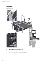
Safety
52
Effects for the cutter
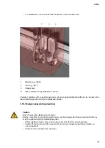
• The drive motors (beams, module carriage) are slowed to a standstill.
• The Z-axis remains in the position where it is located when the safety device is triggered (e.g. lower
position).
• The cutter switches to STOPPED mode.
• Safety-relevant units (modules, tools, etc. ) are stopped and switched off.
• Units that are not safety-
relevant or important for the operation of the machine, such as the operating unit, remain switched on.
• An error message is displayed.
• A warning tone sounds.
Effects on the options connected to the cutter
• Synchornised movements are stopped.
• Units that are not safety-relevant or important for the operation of the machine remain switched on.
Recommissioning
• Restore operational safety.
• Free the light barriers of obstacles.
• Acknowledge the error message on the control panel.
Tip:
If the Z-axis is in the upper or lower position when the safety device is triggered, it is now raised to
the park position.
3.12.2 Control panel
Malfunctions are shown on the LCD display.
An acoustic signal sounds in the event of an error or light barrier interruption or activation of an
EMERGENCY STOP control device.
3.12.3 EMERGENCY STOP control devices
Activating an EMERGENCY STOP control device triggers a machine standstill in the event of an
emergency.
Danger:
Risk of injury due to inaccessible EMERGENCY STOP control device!
Machines with inaccessible EMERGENCY STOP control devices are not safe for operation. The
machine cannot be stopped promptly in hazardous situations.
• Ensure that all EMERGENCY STOP control devices are easy to access and not hidden.
Note:
Risk of damage to the cutter by activating EMERGENCY STOP control devices.
Summary of Contents for S3 M-1200
Page 1: ...Operating Manual S3 Digital Cutter ...
Page 5: ...Contents 5 8 Modules 209 9 Material handling 211 10 Additional specifications 213 ...
Page 6: ...Contents 6 ...
Page 10: ...Introduction 10 ...
Page 14: ...Product description 14 2 5 Cutter overview ...
Page 38: ...Product description 38 ...
Page 64: ...Safety 64 ...
Page 90: ...Controls and operation 90 4 13 3 Inserting replacing the module ...
Page 103: ...Controls and operation 103 Plastic perforated plate Adjustable vacuum range Leather no ...
Page 134: ...Controls and operation 134 ...
Page 155: ...Tips for cutting 155 5 6 2 Calculation of maximum speed for EOT POT Z16 Z42 ...
Page 207: ...Tools 207 7 Tools ...
Page 208: ...Tools 208 ...
Page 209: ...Modules 209 8 Modules ...
Page 210: ...Modules 210 ...
Page 211: ...Material handling 211 9 Material handling ...
Page 212: ...Material handling 212 ...
Page 213: ...Additional specifications 213 10 Additional specifications ...
Page 214: ...Additional specifications 214 ...


