19
TRANSFORMER/FUSE SIZING
NUMBER
OF
DAMPERS
1
40
V
A
1
AMP
40
V
A
1
AMP
2
40
V
A
2
AMP
40
V
A
1
AMP
3
40
V
A
2
AMP
40
V
A
1
AMP
4
40
V
A
3
AMP
40
V
A
2
AMP
5
48
V
A
3
AMP
40
V
A
2
AMP
6
60
V
A
4
AMP
40
V
A
2
AMP
7
72
V
A
5
AMP
40
V
A
3
AMP
8
84
V
A
5
AMP
40
V
A
3
AMP
9
96
V
A
6
AMP
40
V
A
3
AMP
10
108
V
A
6
AMP
40
V
A
3
AMP
11
120
V
A
7
AMP
40
V
A
4
AMP
12
132
V
A
7
AMP
40
V
A
4
AMP
XFMR PWR
FUSE SIZE
Notice: All wiring must meet state and local codes.
TR SERIES (12va)
(SPRING OPEN) DAMPERS
MED. PRESSURE/HEAVY DUTY(2va)
(POWER OPEN) DAMPERS
XFMR PWR
FUSE SIZE
DAMPER TRANSFORMER SIZING
The 24V transformer connected to TR1 and TR2 of the GEN II-R System Controller powers the zone dampers. The power
rating of the transformer must be sufficient to power the number of dampers used. Also, a properly rated in line fuse must be
used on the secondary of the transformer. To determine the power rating of the transformer and the amperage rating of the
fuse, use the table below. If using a combination of spring open and power open dampers, size as if all dampers are spring
open.
DAMPER TRANSFORMER SIZING
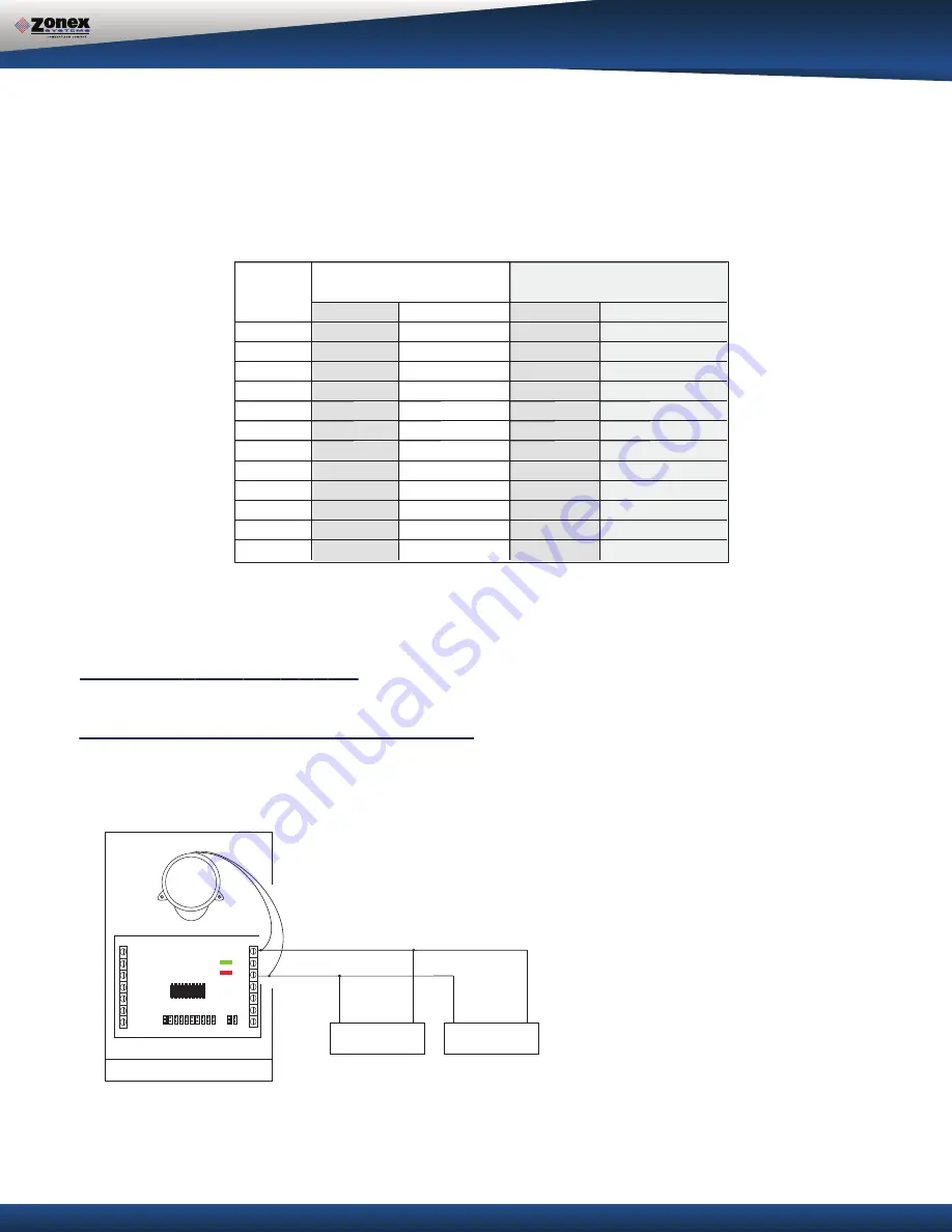
Up to three dampers can be directly controlled by one zone damper control board. To wire two or three dampers for a zone,
use the following wiring diagram. Remember to size the power transformer for the total number of zone dampers in the system,
12va per damper.
SLAVING UP TO THREE 2-WIRE ZONE DAMPERS
SLAVING ZONE DAMPERS
A
A
B
B
RC
MC
RO
E
Y
W/OB
C
R
C
R
ZN1
ZN2
ZN3
ZN4
ZN5
ZN6
ZN7
ZN8
ZN9
ZN10
RUN OPEN
RUN CLOSED
HP
ZONE DAMPER 2
M
M
TRX or TREX damper
TR or TREC damper
ZONE DAMPER 3
M
M
TR or TREC damper


