background image

18

RECTANGULAR ZONE DAMPERS

The rectangular zone dampers are available in either low pressure or heavy duty.  For systems under 5 tons, 

use low pressure dampers.  For systems 5 tons or over, use heavy duty dampers.  Motor drive time open 

and close is 90 seconds.

HEAVY DUTY RECTANGULAR DIMENSIONAL DATA     

Part Number 

STCRX

W x H

Sizes available from 8” x 8” up to 48” x 48”

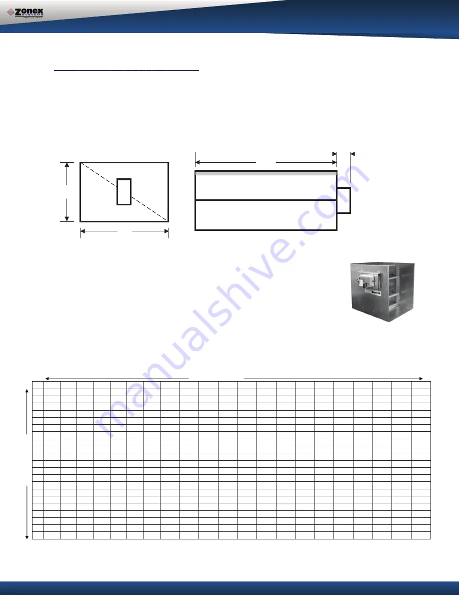
RECTANGULAR HEAVY DUTY ZONE DAMPERS (STCRX)

D

H

MOTOR

D

2 ½”

48” MAXIMUM WIDTH

ZONE DAMPERS


Rectangular Damper Capacities* 

WIDTH IN INCHES 


10 

12 

14 

16 

18 

20 

22 

24 

26 

28 

30 

32 

34 

36 

38 

40 

42 

44 

46 

48 

300 

400 

500 

610 

710 

820 

925 

1050 

1175 

1250 

1400 

1500 

1600 

1725 

1825 

2000 

2100 

2200 

2275 

2400 

2525 

10 

400 

540 

680 

825 

975  1125  1300  1400 

1590 

1750 

1975 

2100 

2175 

2400 

2600 

2775 

2900 

3000 

3200 

3400 

3600 

12 

500 

680 

850  1000  1200  1400  1600  1850 

2000 

2300 

2550 

2700 

2850 

3100 

3400 

3600 

3800 

3975 

4200 

4450 

5775 

14 

610 

825  1000  1250  1500  1750  2000  2250 

2500 

2900 

3150 

3425 

3625 

3825 

4200 

4600 

4800 

5000 

5300 

5750 

6000

16 

710 

975  1200  1500  1800  2100  2450  2700 

3000 

3600 

3950 

4200 

4425 

4650 

5100 

5600 

5780 

6025 

6500 

7000 

7400

18 

820  1125  1400  1750  2100  2500  2850  3080 

3600 

4400 

4600 

4950 

5100 

5600 

6000 

6500 

7000 

7150 

7600 

8100 

8600 

20 

925  1300  1600  2000  2450  2850  3400  3775 

4000 

4800 

5500 

5700 

6000 

6600 

7100 

7900 

8025 

8500 

9000 

9600  10075 

22 

1050  1400  1850  2250  2700  3080  3775  4300 

4800 

5100 

6000 

6350 

6800 

7200 

7800 

8600 

9000 

9600  10000  11500  12500 

24 

1175  1590  2000  2500  3000  3600  4000  4800 

5400 

6100 

7000 

7150 

7600 

8600 

9100  10000  10700  11500  12000  13050  14700 

26 

1250  1750  2300  2900  3600  4400  4800  5100 

6100 

6700 

7800 

8400 

8900  10000  10900  11075  12050  13000  14000  15000  15900 

28 

1400  1975  2550  3150  3950  4600  5500  6000 

7000 

7800 

8400 

9150  10000  10700  11900  13000  13800  14900  15200  16500  17500 

30 

1500  2100  2700  3425  4200  4950  5700  6350 

7150 

8400 

9150  10000  11000  11800  12400  13800  14200  15000  16000  17400  18500 

32 

1600  2175  2850  3625  4425  5100  6000  6800 

7600 

8900  10000  11000  11250  12700  13900  14900  15200  16900  17300  19000  20500 

34 

1725  2400  3100  3825  4650  5600  6600  7200 

8600  10000  10700  11800  12700  14100  15000  16500  17200  18100  19200  20500  21900 

36 

1825  2600  3400  4200  5100  6000  7100  7800 

9100  10900  11900  12400  13900  15000  16100  17400  18500  20000  21500  22900  24200 

38 

2000  2775  3600  4600  5600  6500  7900  8600  10000  11075  13000  13800  14900  16500  17400  17800  20000  21900  22600  24000  25100 

40 

2100  2900  3800  4800  5780  7000  8025  9000  10700  12050  13800  14200  15200  17200  18500  20000  21000  22200  24900  25000  27000 

42 

2200  3000  3975  5000  6025  7150  8500  9600  11500  13000  14900  15000  16900  18100  20000  21900  22200  22800  25100  26900  30000 

44 

2275  3200  4200  5300  6500  7600  9000  10000  12000  14000  15200  16000  17300  19200  21500  22600  24900  25100  26500  30000  32000 

46 

2400  3400  4450  5750  7000  8100  9600  11500  13050  15000  16500  17400  19000  20500  22900  24000  25000  26900  30000  30500  32800 

48 

2525  3600  5775  6000  7400  8600  1075  12500  14700  15900  17500  18500  20500  21900  24200  25100  27000  30000  32000  32800  35600 

* These air quantities were derived from duct sizing chart .1" friction loss per 100' of duct.  All CF


 .

e

t

a

m

i

x

o

r

p

p

a


e

r

a


d

e

t

s

il


s

M

   For accurate selection use duct sizing table or 

H

EI

G

H

T I

N

 INCH

ES


Zonex Systems rectangular heavy duty dampers are recommended for systems 5 tons 

or larger with a maximum differential static psure of 1.75”. These are power open / 

power closed dampers made of 20 gauge “snaplock” steel frame with S & Drive duct 

connections. Allow a 16” gap in the duct for the damper. A full stall motor, drawing 2 VA, 

drives the motor from full open to full close in 90 seconds.

Summary of Contents for GEN II-R

Page 1: ...R Installation and Applications Manual Control 2 10 Zones with 2 or 3 Wire Dampers using Standard Thermostats with only 1 Gen II R per System Residential Light Commercial Zoning utilizing 2 postion zo...

Page 2: ...ntrol board R C Y W OB and E if using emergancy heat in Heat Pump operation 10 Address the the first damper control board jumper as 1 see pages 10 and 11 for thermostat installation and addressing Not...

Page 3: ...the factory on one pin for normal gas heat operation where the fan is controlled by the HVAC system fan control When a fan output is required from the GEN II R controller on a call for heat place the...

Page 4: ...g Schematic 4 DAMPER CONTROL BOARD THERMOSTAT SELECTION Round and Rectangular Damper Selection Sizing Sizing Transformer Based on Damper Count Slaving Zone Dampers 10 ZONE DAMPERS 2 OR 3 WIRE SELECTIO...

Page 5: ...lay fully adjustable capacity control with on board limit settings and optional staging strategies The system provides the installing contractor with a simple startup diagnostic to minimize wiring err...

Page 6: ...SFORMER 5 TONS AND UNDER OVER 5 TONS BAROMETRIC BYPASS Round 101ABBD diam Rectangular RBB W x H BYPASS DAMPER ELECTRONIC MODULATING BYPASS DAMPER Includes Integrated Static Pressure Control Round STBP...

Page 7: ...y selected When the GEN II R controller changes modes a 5 minute purge cycle is initiated before the changeover is completed On active heat or cool calls the non calling zones will close When the last...

Page 8: ...er out to Dampers R C 18 ga thermostat wire TR1 TR2 Damper Power Daisy Chain Damper to Damper 18GA Thermostat wire GAS ELECTRIC OPERATION GEN II R 7 2 SET DN UP S S GND B ON AUTO TIME TMP TIME EH O B...

Page 9: ...han 40 F 4 C 3 RAISE Press the DN button after C is displayed immediately release the DN button and press the UP button Hold until the desired temperature reading is displayed and release 4 Press the...

Page 10: ...SET and DN buttons H simultaneously When delay time appears in the display release the buttons and immediately press the DN button and hold until the desired delay time is displayed and release To ve...

Page 11: ...alibrated to the controller at the factory However the calibration should be checked as part of the system setup procedures If adjustments are required use the Blue potentiometer labeled R44 located i...

Page 12: ...a 5 minute purge cycle with all supply dampers closing then all dampers modulate open for ventilation GENERAL INSTALLATION INSTRUCTIONS for 5 minutes Heat Pump operation B reversing valve By placing t...

Page 13: ...oller is configured for Heat Pump HP jumper F on both pins the Cool Heat cut out temperatures are 45 126 F 7 52 C The cut out temperatures can be changed with the following procedure Heat cut out temp...

Page 14: ...control board must have a unique address from 1 10 To set the damper control board address there is a jumper on the board Find the first damper in the daisy chain and place the jumper on ZN1 for addr...

Page 15: ...at Cool 7 day programable thermostat Note For heat pump operation with emergency heat install one heat pump thermostat with emergency heat operation on any zone WIRING TO A GAS ELECTRIC THERMOSTAT A A...

Page 16: ...MPER ZONE DAMPER DM 2 A A B B RC MC RO E Y W OB C R C R ZN1 ZN2 ZN3 ZN4 ZN5 ZN6 ZN7 ZN8 ZN9 ZN10 RUN OPEN RUN CLOSED ZONE DAMPER DM 3 A A B B RC MC RO E Y W OB C R C R ZN1 ZN2 ZN3 ZN4 ZN5 ZN6 ZN7 ZN8...

Page 17: ...W2 G R HP GE O B R Y1 Y2 G W2 A HP HP HP S S TR1 TR2 TR1 TR2 A A B B RC MC RO E Y W OB C R C R ZN1 ZN2 ZN3 ZN4 ZN5 ZN6 ZN7 ZN8 ZN9 ZN10 RUN OPEN RUN CLOSED HP 24V POWER IN 24V POWER OUT FIELD SUPPLIED...

Page 18: ...st be connected to the GEN II R TR2 terminal Confirm the daisy chain wiring is correct at this time 3 Check A B wires for proper color code and connections polarity is imperative All A connec tions mu...

Page 19: ...ycle times out the opposing thermostat call is initiated and the appropriate HVAC outputs are energized and the supply damper opens The thermostat with the opposing call must now satisfy before the GE...

Page 20: ...r is fully closed and cycle off when the damper is opening or in the full opened position Since this is a spring open damper in the event of power failure the damper fails to the full open position RE...

Page 21: ...s to the maximum static pressure drop in inches of water column between the input upstream of the zone damper and the output downstream when the damper is closed DUCT DIAMETER NOMINAL CFM DUCT VELOCIT...

Page 22: ...0 7000 7800 8400 9150 10000 10700 11900 13000 13800 14900 15200 16500 17500 30 1500 2100 2700 3425 4200 4950 5700 6350 7150 8400 9150 10000 11000 11800 12400 13800 14200 15000 16000 17400 18500 32 160...

Page 23: ...ansformer must be sufficient to power the number of dampers used Also a properly rated in line fuse must be used on the secondary of the transformer To determine the power rating of the transformer an...

Page 24: ...or STCD damper ZONE DAMPER 2 MC RO RC ZONE DAMPER 3 MC RO RC 24 VOLT TRANSFORMER CONTROL RELAY SPST CONTROL RELAY SPST ZONE DAMPER 1 MC RO RC STMPD or STCD damper STMPD or STCD damper STMPD or STCD d...

Page 25: ...installed in any position The RBB rectangular damper must be installed with horizontal air flow only SIZING When only the smallest zone is calling the maximum amount of excess supply air flow through...

Page 26: ...Be certain the damper shaft is horizontal c Loosen counter weight with allen wrench d Loosen lever arm from damper shaft and allow to hang straight down e Fully close damper by grabbing damper shaft...

Page 27: ...r ROUND BYPASS DAMPER SELECTION The Zonex Systems STBP damper is used for round bypass applications When you know the bypass CFM requirements use the ROUND BYPASS SELECTION TABLE to confirm the round...

Page 28: ...4000 4500 5000 5500 6000 14 1167 1458 1750 2042 2333 2625 2917 3208 3500 4083 4667 5250 5833 6417 7000 16 1333 1667 2000 2333 2667 3000 3333 3667 4000 4667 5333 6000 6667 7333 8000 18 1500 1875 2250...

Page 29: ...a dedicated 24vac 40VA transformer 3 Do not install the bypass damper outside 4 Locate the Integrated Pressure Control IPC and air tube on the bypass damper 5 Drill hole into the side of the supply du...

Page 30: ...1 To open all dampers it may be necessary to remove Y outputs to unit on the zone control board and to make full cool calls on all thermostats This will modulate dampers fully open and lock out compr...

Page 31: ...ite http www zonexproducts com Part GENII RMAN PATENTED PRODUCT Zonex Systems reserves the right to discontinue or change at any time specifications or designs without notice and without incurring obl...

Reviews: