background image

4

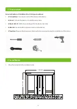
Mark the floor following the periphery of the legs.

4.

1

2

0

.0

1253.00 

7

8

1

.2

1

2

0

.0

Take the turnstile aside and use the electric drill according to the drawn screw holes.

5.

6.

Clean up the soil and dust after the drilling is completed, place the turnstile to the installation site 
again.

Summary of Contents for Mars Pro-F1000

Page 1: ...ion Guide Mars F1000 Mars Pro F1000 Version 1 0 Due to regular upgrades of systems and products ZKTeco could not guarantee exact consistency between the actual product and the written information in this manual ...

Page 2: ...ns 4 1 1 Installation Requirements The installation position of the flap barrier depends on its size A distance of 100mm between the flap barrier and the wall needs to be reserved for ease of opening the top cover of the machine to perform maintenance and adjustment The reference figure is shown below 2 Installation Position 3 Make sure the ground wire of the system is reliably connected to avoid per...

Page 3: ... Screwdriver To remove or install the screw on the device A Pencil To mark the device size and the screw hole A Electric Drill Drill holes according to the marked screw holes A Wrench Secure the M12 expansion screw on the device 4 Installation 1 Place the turnstile to the installation site ...

Page 4: ...4 Installation Remove the screws fixing the top lid and remove the top lid 2 3 Remove the side lid that hang on the device 3 ...

Page 5: ...f the legs 4 120 00 1253 00 781 24 120 00 Take the turnstile aside and use the electric drill according to the drawn screw holes 5 6 Clean up the soil and dust after the drilling is completed place the turnstile to the installation site again ...

Page 6: ...a wrench 7 8 Connect the online cables and perform the power on test If the test is OK install the side lid and top lid of the device M12 Expansion Screw Tether Cable Power Line 100 00 1202 49 180 00 301 24 180 00 301 24 600 00 274 27 274 27 310 94 710 66 ...

Page 7: ...6 Power Supply Air Switch 9 It is recommended that a warning line be marked on the ground after installing the device so as to prompt the pedestrian to stand behind the warning line when verification ...

Page 8: ...10 If you need to assemble the swing arm by yourself please refer to the diagram below for installation Note The swing arm is already installed in the factory 7 ...

Page 9: ...ZKTeco Industrial Park No 32 Industrial Road Tangxia Town Dongguan China Phone 86 769 82109991 Fax 86 755 89602394 www zkteco com Copyright 2021 ZKTECO CO LTD All Rights Reserved ...

Reviews: