Page18 INSTRUCTION MANUAL CENTRAL COMMAND STATIONS MX10, MX10EC
ZIMO
CAN
ZIMO CAN
I/O ribbon cable
(16-pole)
12 V M 30
V
4.
The “Connection and distribution board” MX10AVP
This PCB is available as accessory to the MX10; NOT included in the start sets.
The “Connection and distribution
board” MX10AVP is a connector
board with comfortable sockets and
clamps, which does not have func-
tionality on its own (i.e. no active
electronic components).
The MX10AVP is useful, because
the MX10 has a lot of connectors,
but the space on the front and the
back of the device is limited, which is
why some connectors are combined
into one connection point, like for
example: “CAN 2” (the second CAN
bus) is on the “XNET” (=XpressNet)
socket. For switching rails and simi-
lar there are space-saving pin con-
nectors available on the MX10.
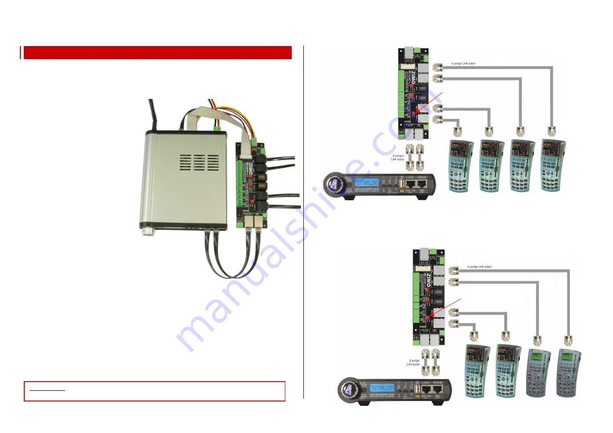
The picture on the right shows the typical
Connection between the central com-
mand station MX10 and the “Connection
and distribution board MX10AVP” with
the cables and connectors supplied. De-
pending on the use, not all of these con-
nections are necessary all the time
.
First Example:
The easiest way to use the “Connection and distribution board
MX10AVP
” is with a
bus distributor
:
while the central command station MX10 itself has two CAN sockets (front and back), this way 5
sockets are available, 4 of them on the MX10AVP. This may be useful despite all devices having two
CAN sockets (for daisy-chaining).
In the MX10 menu “Bus Monitor” “ZIMO2.xx (125)” has to be configured for “CAN1” and
“CAN2”. The MX10AVP’s
jumpers
(next to the sockets CAN 1/2) have to be plugged into
“CAN-1”
.
This way, all 4 CAN sockets are connected in parallel.
As long as the CAN bus only connects controllers of the current generation (like MX32), it doesn’t mat-
ter if the cables of the connection and distribution board MX10AVP to the central command station
MX10 have 6 or 8 poles. For standardisation reasons, 8-pole cables are recommended. To connect the
controllers, usually 6-pole cables are used (more flexible).
Second Example:
New (MX32, MX32FU) and old (MX31, MX31FU) controllers shall be used together; the new genera-
tion devices communicate via a different protocol than the old ones (at least if full functionality shall be
preserved): therefore, in the MX10 menu “Bus Monitor” “CAN1” has to be set to “MX8/9” and
“CAN2” to “ZIMO2.xx (125)”:
the old controllers (latest:
MX31) are connected to CAN-
1, the new (MX32) to CAN-2!
The sockets, to which MX32
controllers are connected,
have to be set to
“CAN-2”
.
Set the
jumpers
on the
MX10AVP accordingly!
The advantage over a direct
connection to the MX10 (with
the “special” cable
8POLA1M
for the MX32) is the control-
ler’s supply by the full “CAN
voltage” of 30V whn charging
the radio controllers.
MX32 MX32 MX31 MX31
Jumpers to “CAN-1”
Jumpers to “CAN-2”
MX32 MX32 MX32 MX32
Connection power supply
ZIMO
CAN
ATTENTION:
only use “normal” 8-pole (or 6-pole) CAN cables with the MX10AVP,
no
“8POLAxM”
special cables!


