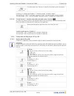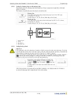
F
out
[Hz]
F
max
= 50 Hz
F
off
26.07.2012
v_u_f_dia_fcontr_d.vsd
1
2
3
4
5
6
7
8
9
10
Analog In 1
0
45
50
40
35
30
25
20
15
10
5
2
4
6
8
10
12
14
16
18
20
0...10 V
0...20 mA
10
20
30
40
50
60
70
80
90
100 0...100 % PWM
F
edge
= 48.5 Hz
U
out
100 %
F
on
0.5
1
5
Q
L
U
start
= 10 %
U
start
= 0 %
Uout
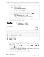
Output voltage
Fout:
Output frequency
Analog In
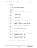
Speed setting signal (0 - 10 V, 0...20 mA, 0...100 % PWM)
Ustart
Startvoltage
Foff
Shutdown Freq.
Fon:
Switch on Freq.
Fedge
Edgefrequency
Fmax
Max. Frequency
L
linear
Q
Square (factory setting)
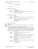
Due to technical reasons the output voltage amounts to approx. max. 95 % of the applied mains
voltage.
In order to still be able to achieve the maximum air
fl
ow of the connected fans, an increase of the
maximum frequency is possible for our motors. For this, a current increase must be included in the
calculation. It is necessary to optimize monitoring of motor current, output voltage, and speed using
suitable measuring instruments.
The factory set values are for voltage controllable external rotor motors with 400 V / 50 Hz.
After veri
fi
cation of the motor speci
fi
cations, adjustments are to be adapted, if applicable.
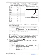
Motor rated voltage
(see Rating plate)
Setting
“
Edgefrequency
”
Setting
“
Max. Frequency
”
3 ~ 400 V, 50 Hz
48.5 Hz
50 Hz
3 ~ 400 V, 50/60 Hz
48.5 Hz
60 Hz
3 ~ 400 V, 60 Hz
57 Hz
60 Hz
Startvoltage
Startvoltage
The start voltage is used to apply enough torque to the motors to insure they will run at
low speed.
Attention! In order to prevent over current and unnecessarily high thermal load of the
motor, do not select to high a setting.
Adjustment range: 0 - 25 % (percentage of the maximum output voltage)
Factory setting: 0 %
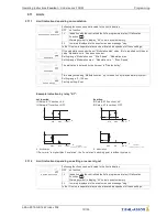
VF quadratic
VF quadratic
U/f curve linear or square
Factory preprogrammed square characteristic curve
“
UF square
”
=
“
ON
”
for the
operation of voltage controllable fans.
For operation with linear curve
“
UF quadratic
”
=
“
OFF
”
Operating Instructions
Fcontrol
–
model series FXDM
Programming
L-BAL-E072-GB 1642 Index 008
Part.-No.
76/105


