ZGR VERSATILE RT - 10 KVA
Manual de operaciones
www.zigor.com
9
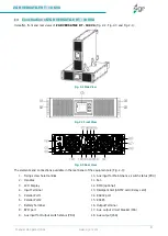
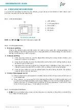
Construction of ZGR VERSATILE RT - 10 KVA
Hereafter, front and rear views of ZGR VERSATILE RT - 10 KVA
(
Fig. 2-2
,
Fig. 2-3
and
Fig. 2-1
)
:
Fig. 2-1 Side View
Fig. 2-2 Front View
Fig. 2-3 Rear View
The elements and connections available in the rear panel of the equipment are (Fig. 2-3):
1.
Fixing screw hole Handles
2.
Handles
3.
LCD Display
4.
Input Terminal
5.
Parallel Port 1
6.
Parallel Port 2
7.
Battery Terminal
8.
EPO port
9.
Aux input for Output switch status (PDU)
10.
Aux input for Maintenance switch status (PDU)
11.
Fan
12.
BMS (optional)
13.
Intelligent Slot (SNMP card/ Relay card)
14.
RS232 port
15.
RS485
16.
Output Terminal
17.
Aux. output circuit breaker (16A)
18.
Aux.output (16A)


