background image

ZGR VERSATILE RT - 10 KVA 


Manual de operaciones 

www.zigor.com 


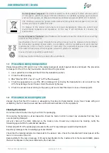
Precautions during transportation 

Please transport the UPS system only in the original package to protect against shock and impact. The procedure 
to transport of the UPS to the final location should follow the procedure: 

1.


Use a pallet truck to transport the UPS to the installation position. 

2.


Check the UPS packing. 

3.


4.


Check the appearance to see if the UPS is damaged or not during the transportation, do not switch on the 
UPS if any damage found. Please contact the dealer right away. 


5.


Check the accessories according to the packing list and contact the dealer in case of missing parts.


Precautions on receiving the unit 

Visually  check  that  the  UPS  location  is  adequate  by  checking  its  characteristics  (clean,  free  of  leaks  with  good 
ventilation); the floor must be level and have sufficient load resistance for the equipment. 


Checking the material 

Do not lean the UPS when moving it out from the packaging. 

On  receiving  the  material,  a  visual  inspection  should  be  made  in  order  to  detect  any  anomalies  that  may  have 
occurred during transport. 

List  and  check  all  the  items  indicated  on  the  delivery  note.  Should  any  component  be  missing,  notify  the 
forwarding agent within the established deadline. 

Extract all parts from the packaging and examine the unit for any damage caused during transport. 

Report any damage to the forwarding agent and ZlGOR. 

Check that the material delivered corresponds to the delivery note. Check the manufacturer's label placed at the 
rear or on one side of the unit. 

Responsibility for the loss or damage of Products shall transfer to the Customer from the moment ZIGOR, places 
these at his disposal in the place indicated by the Customer.


Correct product disposal: This electrical-electronic device (AEE) is marked with the symbol 
of  compliance  with  the  European  Directive  2012/19  /  EU  (WEEE)  regarding  used  electrical 
and electronic equipment (Waste electrical and electronic equipment WEEE, RD 110/2015). 

The Directive provides  the general framework valid throughout  the European Union for the 
removal and reuse of waste from EEE. 

To  dispose  of  this  product  and  ensure  its  proper  management,  follow  the  current  local 
environmental  legislation  and  regulations.  In  this  way  it  will  contribute  to  conserve  the 
environment. 

Correct disposal of batteries: Used batteries are reusable consumer products and a recycling 
process must be carried out. 

Used batteries that do not go through the recycling process must be disposed of according to 
the  instructions  regarding  special  waste,  in  accordance  with  the  regulations  and  environmental 
requirements  in  force  in  each  country  or  community.  This  requirement  applies  in  the  European 
Union and in those places where separate collection systems are available. 

In case of doubt, consult the manufacturer. 

In this way it will contribute to conserve the environment. 

Summary of Contents for VERSATILE RT

Page 1: ...Operation Manual ZGR VERSATILE RT 10 KVA Online Three phase UPS www zigor com ...

Page 2: ...de and transferring 11 3 2 1 Transfer to bypass if overload 11 3 2 2 Normal mode to battery mode 11 3 2 3 Go to bypass mode due to over temperature 11 3 2 4 Output short circuit 12 3 2 5 Battery self Test 12 Turn on off UPS 12 3 3 1 Connecting with Utility 12 3 3 2 Black Cold start procedure 13 3 3 3 Inverter Off 13 3 3 4 Disconnecting with Utility 13 Control panel and monitorization 14 3 4 1 LCD ...

Page 3: ... ZIGOR Reservados todos los derechos No está permitida la reproducción total o parcial de este Manual de Operación ni su transmisión de ninguna forma o por cualquier medio ya sea electrónico o mecánico por fotocopia registro u otro procedimiento de almacenamiento o recuperación de información sin permiso del editor El contenido de este manual es exacto en el momento en que se procede a su impresió...

Page 4: ...h the unit was designed is defined in the documentation The system shall be exposed only to admissible environmental conditions These are defined in the technical details provided for the equipment ZIGOR accepts no responsibility for any inadequate negligent or incorrect installation of the equipment Please follow the indications set out below to operate under conditions of complete safety The Sys...

Page 5: ... ask ZIGOR for assistance Storage precautions The store where the material is kept must protect the material from the elements risk of flooding or contact with water The material shall be protected from any risk of overheating due to exposure to direct sunlight or through windows The recommended storage temperature is from 15ºC to 25ºC An increase of 10ºC can reduce the service life of the battery...

Page 6: ...d during transport Report any damage to the forwarding agent and ZlGOR Check that the material delivered corresponds to the delivery note Check the manufacturer s label placed at the rear or on one side of the unit Responsibility for the loss or damage of Products shall transfer to the Customer from the moment ZIGOR places these at his disposal in the place indicated by the Customer Correct produc...

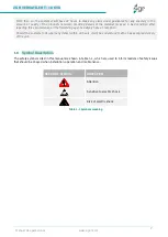
Page 7: ...ion Sensitive to electric shock Risk of electric shock Table 1 1 Symbols meaning From then on the customer will have 24 hours to make any claim under guarantee for any anomaly in the amount or quality of the products received providing details of the material received in bad condition after reporting this circumstance on the forwarding agent s delivery note on reception Should the customer not rep...

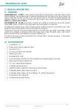
Page 8: ...gh efficiency up to 93 5 The UPS can solve most of the power supply problems such as blackout over voltage under voltage voltage sudden drop oscillating of decreasing extent high voltage pulse voltage fluctuation surge inrush current harmonic distortion THD noise interference frequency fluctuation etc This UPS can be applied to different applications from computer device automatic equipment commun...

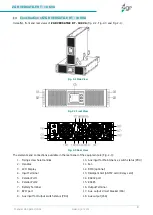
Page 9: ...s and connections available in the rear panel of the equipment are Fig 2 3 1 Fixing screw hole Handles 2 Handles 3 LCD Display 4 Input Terminal 5 Parallel Port 1 6 Parallel Port 2 7 Battery Terminal 8 EPO port 9 Aux input for Output switch status PDU 10 Aux input for Maintenance switch status PDU 11 Fan 12 BMS optional 13 Intelligent Slot SNMP card Relay card 14 RS232 port 15 RS485 16 Output Termi...

Page 10: ...itical AC load There is no power interruption to the critical load The UPS will automatically return to Normal Mode when AC supply recovers Fig 3 2 Fig 3 2 Battery mode 3 1 3 Bypass mode If the inverter is out of order or if overload occurs the static transfer switch will be activated to transfer the load from the inverter supply to bypass supply without interruption to the critical load Fig 3 3 I...

Page 11: ...oad of UPS is beyond normal range and lasts for the time set it will transfer to bypass mode and beeps twice every second and then the load is powered by AC directly Please decrease the load immediately until the alarm is eliminated The UPS will start the inverter after 5 minutes In order to protect the load and the UPS it is required to set the limitation times of transferring to bypass mode due ...

Page 12: ...10 seconds 2 When choosing 10 m UPS can transfer to Battery Mode automatically per 30 days And the Battery Self test Time is 10 minutes 3 When choosing EOD UPS can transfer to Battery Mode automatically per 30 days And the Battery Self test Time is EOD Turn on off UPS 3 3 1 Connecting with Utility according to the user s manual Switch on the UPS The internal fan of the UPS starts spinning the UPS ...

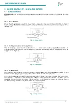
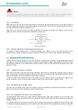
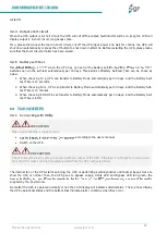
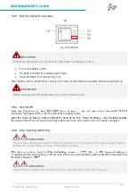
Page 13: ...ng After 60 seconds all the LED on the LCD display extinguish 3 3 4 Disconnecting with Utility completely and fan stops spinning in 60 seconds If there are external battery packs connected please also turn the battery breaker PRECAUTION Follow these procedures when the input AC Utility Failure but battery is normal PRECAUTION Wait for approximately 30 seconds before you press the black start key P...

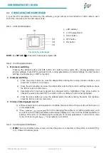
Page 14: ...u 2 Press the arrow button can view the details after entering the function settings interface press the ESC to return to main menu 3 Parameter which has been selected and changed will be highlighted Press arrow button to change the value and press ENT to confirm it Once confirmed it will not be highlighted 4 Press the arrow button can view the detailed alarm info after entering the alarm info int...

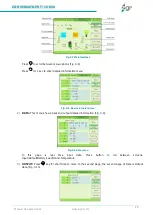
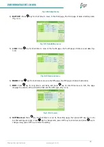
Page 15: ...d information menu Fig 3 8 Basic status interface 2 DATA This menu shows input and output detailed information Fig 3 9 Fig 3 9 Data menu In this page is real time input data Press button to roll between screens Input Output Battery Load Innner temperature 3 OUTPUT Press key for short time to move to the second page the second page of Data is Output data Fig 3 10 ...

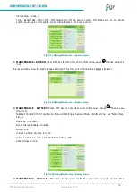
Page 16: ... Data Load menu 6 INSIDE Press key for short time to move to the fifth page the fifth page of data is Inside data 7 INFO Press key for long time to exit Data and press key for short time move to Info this page displays the version of the LCD LED DSP and the UPS type Fig 3 13 Fig 3 13 Info menu 8 SETTING User Press key for short time to move to the setting page then press OFF key Fig 3 14 to enter ...

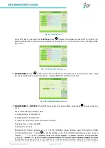
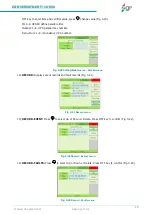
Page 17: ...rsonal Contact ZIGOR for training Fig 3 16 Fig 3 16 Setting Maintenance menu 10 MAINTENANCE SYSTEM Press OFF key to enter item and confirm value press change value Fig 3 17 Work mode Normal Paralado ECO V_Output Grade 220 230 240 V F_Output Grade 50 and 60 Hz F_mode CVCF and Non CVCF Fecuency converter Test type 10 s 10 min and EOD Test Cycle 1 30 days Equipment ID Device address is 1 15 it is the...

Page 18: ...he static bypass will work This limits will will lock unlock bypass transfer Fig 3 18 Setting Maintenance Bypass menu 12 MAINTENANCE BATTERY Press OFF key to enter item and confirm value press change value Fig 3 19 Number 16 18 20 PCS Total Note there are 8 9 10pcs between Bat BatN string BatN Bat string Capacity 7 2000Ah Boost charge Enable or disable Group 1 8 V Boost 2 30 2 40 step is 0 01V V F...

Page 19: ...number Redu Num 1 3 redundancy UPS number Fig 3 20 Setting Maintenance Parallel menu 14 RECORD Displays event records and fault records Fig 3 21 Fig 3 21 Record menu 15 RECORD EVENT Press to select Up or Down or Delete Press OFF key to confirm Fig 3 22 Fig 3 22 Record Events menu 16 RECORD FAULTS Press to select Up or Down or Delete Press OFF key to confirm Fig 3 23 Fig 3 23 Record Faults menu ...

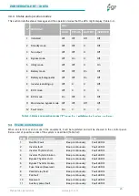
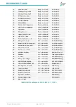
Page 20: ...tion modes Events and status list When an alarm or event occurs in the equipment it will be registered and will be showed in the control panel Below a list of possible events of the system is described Table 3 2 ITEM UPS ALARM WARNING BUZZ LED 1 Rectifier Fault Beep continuously Fault LED lit 2 Inverter fault Beep continuously Fault LED lit 3 Inverter Thyristor short Beep continuously Fault LED li...

Page 21: ... LED lit 26 Battery over voltage Once per second Fault LED blinking 27 Mains volt reverse Reserved Once per second Fault LED blinking 28 Bypass reverse Reserved Once per second Fault LED blinking 29 Output Short circuit Once per second Fault LED blinking 30 Rectifier over current Once per second Fault LED blinking 31 Bypass over current Once per second BPS LED blinking 32 Overload Once per second ...

Page 22: ...s maintained between 15 C and 25 C Keep batteries away from heat sources or main air ventilation area etc Should the equipment not be installed immediately it must be stored in a room so as to protect it against excessive humidity and or heat sources The highest altitude that UPS may work normally with full load is 1500 meters The load capacity should be reduced when this UPS is installed in place...

Page 23: ... may avoid the risk of UPS overloaded Over current Protection device shall be installed at the distribution panel of the incoming main supply It may identify the power cables current capacity as well as the overload capacity of the system 4 3 2 Power Cables connection Once the equipment has been finally positioned and secured connect the power cables as described in the following procedure Verify ...

Page 24: ...Positive Bat Neutral Bat Negative Right Output Ground Output Neutral Output L AC Input UPS Input UPS Output Output Load Fig 4 2 Connections Choose appropriate power cable and pay attention to the diameter of the connection terminal of the cable that should be greater than or equal to that of the connection poles Fig 4 1 to Fig 4 4 Fig 4 3 Three phase in Single phase out ...

Page 25: ... and the AC bypass supplies must be referenced to the same neutral point WARNING If the load equipment is not ready to accept power until the arrival of the commissioning engineer then ensure that the system output cables are safely isolated at their ends WARNING The earthing and middle point bonding arrangement must be in accordance with local and national codes of practice WARNING Upon starting ...

Page 26: ...tive battery the BAT is connected to the negative of the negative battery Factory default setting for battery quantity is 16 pcs and for battery capacity is 7 AH charger current 1 A When connecting 18 pcs or 20 pcs batteries please re set battery quantity and its capacity after UPS starts at AC mode Charger current could be adjusted automatically according to battery capacity selected Also charger...

Page 27: ...m info Monitor UPS running parameters Timing off on setting 4 4 2 RS232 communication port definition Fig 4 7 Definition of Male port RS232 PC RS232 PORT UPS RS232 PORT Pin 2 Pin 2 UPS send PC receive Pin 3 Pin 3 PC send UPS receive Pin 5 Pin 5 Ground Table 4 3 Connection between PC RS232 port and UPS RS232 port Available function of RS232 Monitor UPS power status Monitor UPS alarm info Monitor UP...

Page 28: ...f the same rating and be connected to the same bypass source 2 The Bypass and the Main input sources must be follow the same phase secuence 3 The Bypass and the Main input sources must be referenced to the same middle point potential neutral 4 The outputs of all the UPS modules must be connected to a common output bus L N PE 5 In case of common battery system BAT BAT N BAT must be wired correctly ...

Page 29: ...o first startup procedure 1 Be sure all breakers are in OFF position 2 Close AC output breaker 3 Close battery cabinet breakers to energize UPS control board 4 Finally close AC input breaker and wait until end of initializing process 1min If any alarm is shown take note and contalt ZIGOR Service Support WARNING Due to this UPS system is based on 3phase input and 1phase output in case of failure an...

Page 30: ...nection and re do 4 button A pressing ON button time is insufficient B Overload A Press and hold On button for 1s B Disconnect all loads and restart 5 AC indicator blinking Input AC is beyond normal range Pay attention to the backup time if the UPS is in battery mode 6 Abnormal backup time A Battery not fully charged B Battery Bad A Charge battery for 8 hours when AC is normal then test the backup...

Page 31: ...h of sporadic or repetitive failures o Check nothing blocks the ventilation of the front rear and side panel and the case bottom 6 monthly o Check on the correct ventilation of the location o Cleaning of the equipment s air inlet filters o Removal of foreign bodies both in the air inlet and outlet o Visual verification of the status of connecting wires rusting damage to insulation etc Annually o C...

Page 32: ...s series standard models Battery life depends on environment temperature and discharge charge cycles it will be shortened if temperature raised or deep discharged Periodical maintenance is required so as to keep battery in good condition 1 The most proper working temperature is 15 to 25 ºC 2 Avoid small discharging current for 24 hours 3 Charge battery for at least 12 hours every 3 months if it is...

Page 33: ...hase ground L N PE Output precision 1 0 Voltage distortion THD 2 at 100 linear load 5 at 100 non linear load Rating voltage 220 230 240 V Frequency 50 Hz 60 Hz Frequency precision 0 1 Overload 105 110 1 h 110 125 10 min 125 150 1 min 150 immediate Crest factor 3 1 Efficiency at normal Up to 93 5 Switch time Between Normal mode and battery mode 0 ms Between inverter and bypass 0 ms Unlock 15 ms 50 ...

Page 34: ...rotection IP20 OTHERS Noise level 55 dB 1 m Operation temperature 0 ºC 40 ºC Relative humidity 0 95 sin condensación Dimensions W x D x H 443 x 131 x 580 mm Approx Weight kg 28 kg STANDARDS Marks CE Directives EN 60950 1 EN 62040 1 IEC 62040 2 IEC 62040 3 ROHS ZIGOR ...

Page 35: ...bed in this manual comply with the following European regulations I Directive 2014 35 EU Low Voltage Safety LVD for Uninterruptible Power Supply UPS Standard EN 62040 1 2008 A1 2013 II Directive 2014 30 EU Electromagnetic Compatibility EMC Standard IEC EN 62040 2 III Comply SAI UPS Clasification EN 62040 3 2011 ...

Page 36: ...ting annual referring to the Installation Conditions When the customer not clearly proves the systematic realization of regular maintenance operations described in the Operating Manual Equipment deterioration due to external agents water dirt animals etc Damages caused by accident theft fire inadmissible atmospheric conditions external agents animals insects etc or natural disasters In case of any...

Page 37: ...7 Zigor Corporación Portal de Gamarra 28 01013 Vitoria Gasteiz Álava Spain 34 945 21 46 00 www zigor com Consulte nuestra web para contactar con la red de delegaciones comerciales Refer to our website in order to contact the commercial branches network ...

Reviews: