

2 • Introduction
Important User Information
Copyright © 2021 Zero Zone, Inc.
all rights reserved. No part of the contents of this manual may be reproduced, copied, or transmitted in any form or by any means including
graphic, electronic, or mechanical methods or photocopying, recording, or information storage and retrieval systems without the written
permission of the publisher, Zero Zone, unless it is for the purchaser’s personal use.
The information in this manual is subject to change without notice and does not represent a commitment on the part of Zero Zone. Zero Zone
does not assume any responsibility for any errors that may appear in this manual. In no event will Zero Zone be liable for technical or editorial
omissions made herein, nor for direct, indirect, special, incidental, or consequential damages resulting from the use or defect of this manual.
The information in this document is not intended to cover all possible conditions and situations that might occur. The end user must exercise
caution and common sense when installing, using, or maintaining Zero Zone products. Zero Zone products should only be installed by qualified,
professional refrigeration technicians. If any questions or problems arise, call Zero Zone at 800-247-4496.
any change to a Zero Zone product made during the installation, start-up, or at any other time must be submitted in writing to Zero Zone for
approval and be approved by Zero Zone in writing prior to commission. The product warranty is voided when any unapproved change is made
to a Zero Zone product.
Manufacturer
Zero Zone, Inc.
Display Case Division
110 N Oakridge Dr • North Prairie, WI 53153 • 800-247-4496 • www.zero-zone.com
Intended Use
Zero Zone products are intended to be installed and used as described in this manual and other related Zero Zone literature, specifications,
drawings, and data. all Zero Zone products must be leveled after being installed.
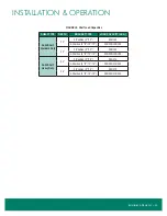
Display Case Models
The information contained in this manual pertains to the following Zero Zone display cases:
CASE MODEL
DESCRIPTION
DOOR SIZE & TYPE
ORMC83D
83" Standard Multi-Deck with Doors
24" x 69" CoolView
®
Ultra
™
French Doors
ORMC88D
88" Tall Multi-Deck with Doors
24" x 74" CoolView
®
Ultra
™
French Doors
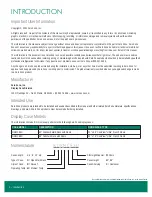
Nomenclature
INTRODUCTION
Sill Height/Special: D=Doors
Case Height:
83", 88"
Case Shelving:
C = Cantilever
Case Length:
4', 6', 8', 12', etc.
Type of Case: O = Open Multi-Deck
Style of Case: R = Reveal
™
Operating Temp: M = Medium Temp
8 O R M C 83 D
Reveal Merchandiser
®
is a registered trademark of Zero Zone, Inc. in the United States.