


39
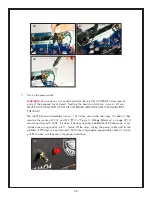
WARNING:
Capacitors contain high-voltage electricity hours after the amp is unplugged!
Handling the capacitor could shock or burn you! If you must remove or re-solder a capacitor,
either let it sit unplugged overnight, or safely discharge it as described in the tip below.
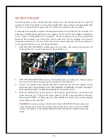
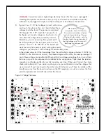
8. Figure 3 has 11 DC test voltages (in red) with arrows
pointing to the place on the circuit board where these
voltages should be found. The points are numbered
TP1 through TP11 (“TP” stands for “test point”). In
the figure next to each voltage is a box for you to
write down the voltage that you actually measure.
Remember, you are measuring from ground (with
the black probe) to the red point (with the red
probe).
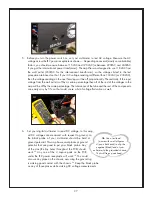
116
Start on the left side of the board and
work your way from point to point, writing down each
voltage as you measure it. All the voltages should be fairly close
to the printed value, but if the line voltage (from the wall outlet) is above or below 118 VAC (or
230VAC for the international version), then these voltages will be off by the same percentage. If
any of these voltages are significantly off beyond this line voltage percentage, then it is very likely
that one or more of the components are installed in the wrong place. Triple check the resistors,
capacitors, and bridge rectifiers by visually inspecting each one. If they are all correct, then triple
check each solder joint. If you make any changes, use your multimeter to re-test the voltages that
were incorrect. If you have to get to the solder side of the board, you’ll have to unsolder all the
transformer wires from the board, and remove the IEC receptacle, as well as unscrew the front
panel components and stand off screws from the chassis.
Figure 3: Voltage Reference
TIP:
To safely discharge
a capacitor: Get a 1k-10k ohm,
2w resistor and solder or clip test
leads to the resistor legs. Clip one
of the leads to the chassis, and clip
the other lead to the positive side of
the high-voltage cap. The cap will
discharge in a few seconds.