


37
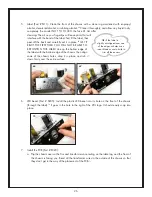
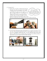
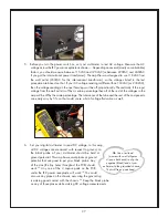
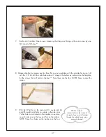
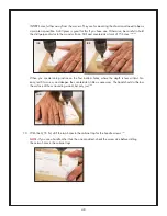
5. Before you turn the power switch on, set your multimeter to test AC voltage. Measure the AC
voltage across the IEC power receptacle as shown.
111
Depending on several (mostly uncontrollable)
factors, you should measure between 115VAC and 120VAC (or between 220VAC and 240VAC
if you got the international power transformer). The amplifier was designed to use 118VAC from
the wall outlet (230VAC for the international transformer), so the voltages listed in the test
procedure are based on that. If your AC voltage reading is different than 118VAC (or 230VAC),
then the voltage readings in the next few steps will be off proportionally. Theoretically, if the input
voltage from the wall outlet is off by a certain percentage then all of the rest of the voltages in the
amp will be off by the same percentage. The tolerances of the tube and the rest of the components
can easily vary by 5%, so that could cause a bit of voltage fluctuation as well.
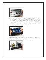
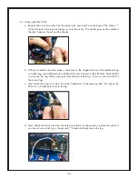
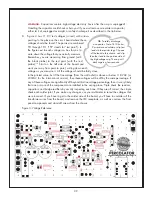
6. Set your digital multimeter to read DC voltage. In this amp,
all DC voltages are measured with respect to ground, so
the black probe of your multimeter should be held at
ground potential. This amp has several places at ground
potential that are good to put your black probe. Any
of the vias (the tiny holes throughout the PCB) should
work.
112
Any one of the 3 square pads on the PCB
under the IEC power receptacle will work.
113
You could
also use any place on the chassis, assuming the ground lug
is making good contact with the chassis.
114
Keep the black probe
on any of those places while making DC voltage measurements.
111
TIP:
Use a test lead
(a wire with small alligator
clips on both ends) to clip the
negative (black) lead of your
multimeter to the grounded chassis.
That will free up one hand.
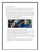
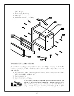
TESTING THE AMP
The testing process is done with the Percolator upside down. The transformers and fins should be
resting on the bench top. Make sure none of the weight of the amp is resting on the glass bottle of the
tube. If it is, put some blocks of wood under the transformers to jack the amp up a little bit.
A schematic of the amplifier is printed on the template sheet that came with the kit. This schematic is for
reference in troubleshooting, should you have problems with the amp. DC test voltages are labeled in
red on “Figure 3: Voltage Reference” on page 39. The test procedure will consist of systematically
measuring these voltages to ensure that your amp is within spec. Print this diagram and write your
measurements directly on it. You don’t have to know how to read a schematic to test these voltages, but
you do need to know how to use your digital multimeter.
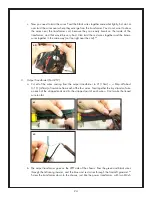
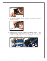
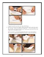
1. WITH THE AMP UNPLUGGED, double check all your wiring. Look closely at the pictures and
make sure the wires on your amp are correctly positioned.
108,109
2. WITH THE AMP UNPLUGGED from the wall, double check your solder joints. Closely examine
every joint on the PCB and make sure they are good, solid connections.
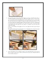
3. Using a 1/4” speaker cable, plug the Percolator’s output jack into an 8 ohm speaker cabinet.
ONLY USE AN 8 OHM CABINET WITH THIS AMPLIFIER. WHENEVER YOU APPLY POWER TO
THIS AMP, MAKE SURE IT IS FIRST PLUGGED IN TO AN 8 OHM LOAD.
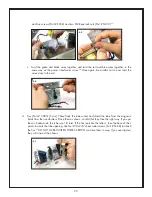
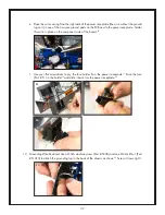
4. Make sure the Percolator’s power switch is in the off position (when the amp is upside down, the
switch should be up).
110
Plug the IEC power cable into the IEC power receptacle on the amp.
Make sure NOTHING is touching any part of the amplifier that shouldn’t be, and then plug the
power cable into the wall outlet.
WARNING!
As soon as you plug in the Percolator, there is LINE VOLTAGE across some parts
of the exposed circuit board. Touching the board could shock, injure, or kill you! NEVER
TOUCH ANY PART OF THE CIRCUIT BOARD WHEN THE AMP IS PLUGGED INTO THE
WALL!
108
109
110