


34
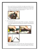
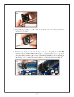
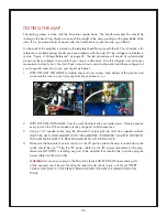
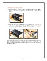
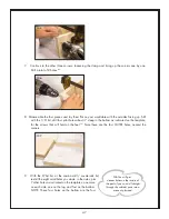
14. Output jack (Part # J2):
a. Remove the nut and washer from the output jack and install it on the back of the chassis.
101
Orient the jack so the lugs are facing up, as in the picture. The washer goes on the outside of
the jack, between the nut and the chassis.
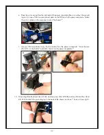
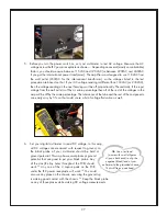
b. With your needle nose pliers make a small hook in the stripped section of the feedback loop
wire (the long wire attached to the middle of the circuit board, in the FBL hole). Hook the FBL
wire on the “tip” lug of the output jack (note the picture below
102
, if you are not sure which is
the correct lug).
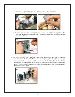
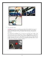
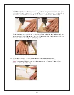
c. Next attach the green wire from the output transformer to the same lug (the “tip” lug) as the
FBL wire.
102
Solder both wires to the lug.
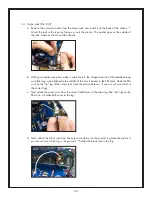
d. Next, attach the black wire from the output transformer to the ground lug (note the picture if
you are not sure which lug is the ground).
103
Solder the black wire to the lug.
101
102
103