


24
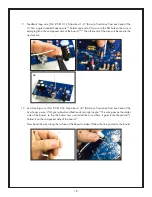
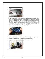
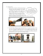
c. Now you need to twist the wires. Twist the black wires together somewhat tightly, but do not
over twist the wires near where they emerge from the transformer. You do not want to stress
the wires near the transformer coil, because they can easily break on the inside of the
transformer, and that would be very bad. Also twist the red wires together and the brown
wires together in the same way (not too tight near the coil).
60
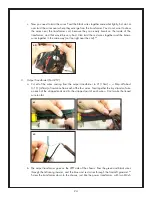
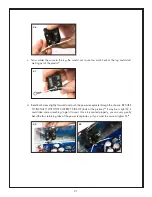
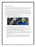
3. Output Transformer (Part # T2):
a. Cut all of the wires coming from the output transformer to 4” (10cm).
61, 62
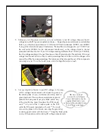
Strip off about
3/16” (4-5mm) of insulation from each of the four wires. Twist together the tiny strands of wire
on each of the stripped ends and tin the stripped part of each wire.
63
Don’t make the tinned
wire too fat.
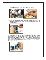
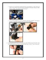
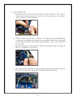
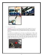
b. The output transformer goes on the LEFT side of the chassis. Pass the green and black wires
through the left-rear grommet, and the blue and red wires through the front-left grommet.
64
Screw the transformer down to the chassis, just like the power transformer, with two M3x6
60
61
62
63