


16
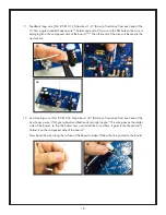
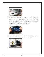
7. Input jack (Part # J1): Remove the plastic nut from the input jack and put it aside until the next
section. Snap the input jack into its holes on the circuit board.
25
Make sure you solder the leads
well.
26
The leads are too short to cut on this component so don’t bother.
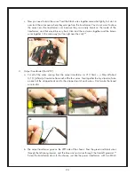
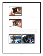
8. Potentiometer (Part # VR1): Remove the nut and washer from the shaft of the pot and put them
aside until the next section. Install the potentiometer (“pot” for short) with the shaft facing away
from the board. The leads are too short to bend out, so you just have to hold the pot while you
solder at least one lead.
27
It is very important to make sure all the leads are completely seated in
their holes before soldering, otherwise the board won’t fit into the chassis properly. The leads are
too short to cut on this component too.
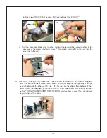
9. Power switch (Part # S1): Carefully install the power switch on the PCB.
28
If all the leads don’t line
up right away, very gently guide them into the holes with your needle-nose pliers.
29
When you
solder the switch, it is very important to make sure all the leads are making good connections with
25
26
27
24