background image


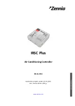
                   IRSC Plus


http://www.zennio.com


Technical Support:


http://support.zennio.com


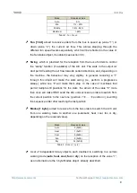
Mode 

Received value 

Auto 

0% 

Min 

1% - 33% 

Middle 

34% - 66% 

Maximum 

> 66% 

Table 1. 

Fan Speed


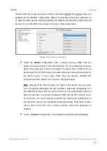
Fan [1 bit]

, aimed to receive orders from the bus  to speed up 

(value “1”) or 

down  (value  “0”)  the  current  air  flow.  This  allows  stepping  through  the 

different fan speed levels sequentially, which will be reflected in the value of 

the fan status object, if enabled (see section 3.3). 


Swing

,  which  is  provided for  the reception  from the  bus  of  orders to  control 

the  “swing”  function  (if  available)  of  the  A/C  unit.  The  slats  in the  output  air 

duct permit leading the air flow towards certain directions, and, depending on 

the  machine,  the  behaviour  may  vary  slightly.  In  general,  receiving  a 

“1” 

through  this  object  will  make  the  slats 

swing

  (i.e.,  perform  a  progressive 

sweep),  while  one 

“0”  will  make  them  stop.  In  the  case  of  machines  that 

permit  multiple  still  positions  for  the  slats,  the  arrival  of  the  value 

“0”  more 

than once will make IRSC send the A/C unit successive orders to switch from 

the current position to the next one (

position 1


… 


position n

), reverting 

the sequence order after reaching the last position. 


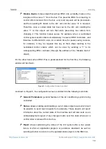
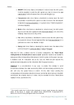
Modes [1 byte]

, aimed to receive from the bus orders to switch the A/C unit 

from  one  working  mode  to  another  one  (automatic,  heat,  cool,  fan  or  dry, 

depending on the received value). 

Mode 

Received value 

Auto 

0 (0x00) 

Heat 

1 (0x01) 

Cool 

3 (0x03) 

Fan 

9 (0x09) 

Dry 

14 (0x0E) 

Table 2. 

Modes (1 byte)


  A  set  of  independent  binary  objects,  each  destined  to  switching  to  a  certain 

working mode (

auto

heat, cool, fan 

or

 dry

) on the reception of the value 

“1”, 

as an alternative to the 1-byte Modes object, already described. 

Summary of Contents for IRSC Plus

Page 1: ...IRSC Plus Air Conditioning Controller ZN1CL IRSC USER MANUAL Application program version 6 12 8 0 User manual edition 8 0 _a www zennio com...

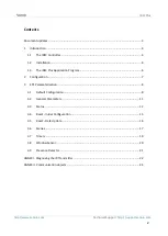
Page 2: ...4 1 3 The IRSC Plus Application Program 6 2 Configuration 7 3 ETS Parameterisation 8 3 1 Default Configuration 8 3 2 General Parameters 11 3 3 Status 12 3 4 Reset Initial Configuration 13 3 5 Reset Da...

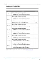
Page 3: ...Open Window function 20 6 11 _a Changes in the application program Additional split models available for control 6 10 _a Changes in the application program Additional split models available for contr...

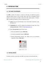
Page 4: ...ctions into the same device Control of the main functionalities of A C units On Off temperature mode fan speed etc Compatibility with most air conditioning manufacturers please refer to the correspond...

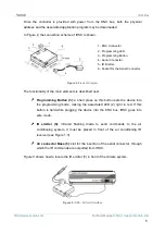
Page 5: ...ing the associated LED 2 light in red If this button is held while plugging the device into the KNX bus IRSC goes into safe mode IR emitter 5 infrared flashing diode to send commands to the air condit...

Page 6: ...common air conditioning systems via IR commands This application allows sending control orders to the A C system through infrared commands with IRSC acting as a KNX IR interface as explained in Secti...

Page 7: ...ver the following functionalities of the A C system can be configured ON OFF control of the A C system Status Objects which also work as acknowledgement objects for the orders sent to the system Worki...

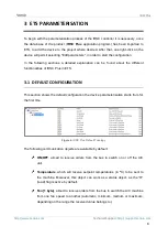
Page 8: ...nt functionalities of IRSC Plus in ETS 3 1 DEFAULT CONFIGURATION This section shows the default configuration the device parameterisation starts from for the first time Figure 4 IRSC Plus Default Topo...

Page 9: ...iving a 1 through this object will make the slats swing i e perform a progressive sweep while one 0 will make them stop In the case of machines that permit multiple still positions for the slats the a...

Page 10: ...sed control orders which can be done by sending a 1 to its corresponding IRSC controller through the address of the Disable device object On the other hand when IRSC Plus is parameterised for the firs...

Page 11: ...to be controlled These are the following Split Model sets a code between 0 and 255 associated to the model of the IR remote of the system to be controlled please refer to the correspondence table at h...

Page 12: ...meterised temperature limitation effectively applied in such case the system will always keep the setpoint over the lower limit for Cool mode and under the upper limit for Heat mode truncating it when...

Page 13: ...tain integer value according to the currently active mode according to Table 2 Fan enables the Fan status 1 byte object which shows the current fan speed in percentage of the A C system according to T...

Page 14: ...wever after a download or a device reset from ETS the previous status will be lost during the download or the device reset in such case IRSC Plus will assume ON OFF Off Temperature 25 C Mode Cool Fan...

Page 15: ...or a device reset the status of the slats can be set to Last saved status1 Swing or Stopped Note that for both a default and for a custom configuration the Send Reset Configuration to the Split when r...

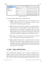
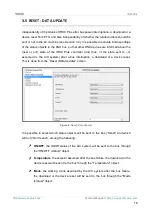
Page 16: ...the state sent to or assumed in the A C system after a bus interruption a download or a device reset This is done from the Reset Data Update screen Figure 8 Reset Data Update It is possible to select...

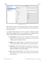
Page 17: ...cts should have been enabled see section 3 3 in order to have these values effectively sent to the bus Important if this sending is not enabled the KNX bus will definitively not be informed about the...

Page 18: ...mosphere to be generated Scene Number the numeric value 1 to 64 on whose arrival from the bus through the Scenes 1 byte object decreased by one 0 to 63 the air conditioning system will execute the sce...

Page 19: ...n and off can be independently enabled and configured After activating the Automatic OFF the Fixed Auto OFF 1 bit object will appear and the following parameters will also be shown in ETS Automatic OF...

Page 20: ...igured waiting period and then it will send a switch off order to the A C system When the window is closed again Window sensor 0 the A C system will be automatically switched on it will not be necessa...

Page 21: ...the time period in minutes that IRSC Plus should wait after receiving the value 0 empty room through the detection object before switching the A C unit off As soon as the Presence detection object rec...

Page 22: ...1IR ZAS and ZN1IRZ38 of any of the various Zennio devices capable of receiving IR signals ZAS InZennio Z38i ACTinBOX Hybrid ACTinBOX MAX6 or ACTinBOX QUATRO One of these devices will be therefore requ...

Page 23: ...er device ZAS InZennio Z38i ACTinBOX Hybrid ACTinBOX MAX6 or ACTinBOX QUATRO of the signals generated by the emitter and therefore whether IRSC Plus is behaving anomalously or not Important it is high...

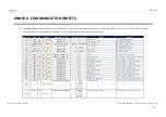
Page 24: ...T W U DPST 1 1 DPST 1 10 0 1 Swing 1 Swing 0 Stop Step 7 1 Bit O C T R DPST 1 1 DPST 1 10 0 1 Swing status Swing state 0 Stopped 1 Swing 8 1 Bit I C T W U DPT_Switch 0 1 Heat Mode 1 Set mode 0 Nothing...

Page 25: ...Auto OFF 1bit 1 Sw OFF after param value 23 1 Bit I O C R W U DPT_Start 0 1 Fixed Auto ON 1bit 1 Sw ON after param value 24 1 Bit I C W U DPT_Bool 0 1 Presence Detection 0 Empty Room 1 Presence 25 1...

Page 26: ...d us your inquiries about Zennio devices http suppot zennio com Zennio Avance y Tecnolog a S L C R o Jarama 132 Nave P 8 11 45007 Toledo Spain Tel 34 925 232 002 Fax 34 925 337 310 www zennio com info...

Reviews: