background image

- 5-4 -

Summary of Contents for XBS341 Series

Page 1: ...SERVICE MANUAL MODELS XBS341...

Page 2: ...R PART ELECTRICAL ADJUSTMENT PROCEDURES 3 1 VCR ELECTRICAL TROUBLESHOOTING 3 2 VCR SHEMATIC DIAGRAMS 3 17 VCR VOLTAGE SHEET IC TR 3 27 PRINTED CIRCUIT DIAGRAMS 3 29 SECTION 4 MECHANSIM OF VCR PART 4 1...

Page 3: ...OT EMIT X RAYS WHEN THE HIGH VOLTAGE IS AT THE FACTORY SPECIFIED LEVEL THE PROPER VALUE IS GIVEN IN THE APPLICABLE SCHEMATIC OPERA TION AT HIGHER VOLTAGES MAY CAUSE A FAILURE OF THE PIC TURE TUBE OR H...

Page 4: ...ams may damage the eyes Absolutely never permit laser beams to enter the eyes Also NEVER switch ON the power to the laser output part lens etc of the pick up if it is damaged 5 Cleaning the lens surfa...

Page 5: ...replacing a component part first disconnect the power supply lead wire from the unit 2 All equipment measuring instruments and tools must be grounded 3 The workbench should be covered with a conducti...

Page 6: ...Accessible Conductive Parts including Metal pan els Input terminals Earphone jacks etc Electrostatically Sensitive ES Devices Some semiconductor solid state devices can be damaged easily by static ele...

Page 7: ...arges sufficient to damage ESD devices 5 Do not use freon propelled chemicals These can generate electrical charges sufficient to damage ESD devices 6 Do not remove a replacement ESD device from its p...

Page 8: ...n azimuth system Timer 12 hour display type with AM PM Tape speed SP 33 35 mm sec LP 16 67 mm sec SLP 11 12 mm sec Tape width 12 7 mm Maximum recording time SP 2 HOURS T 120 SLP 6 HOURS T 120 8 HOURS...

Page 9: ...Rated Input Power 20W Max Input Power 40W Net Dimensions W x H x D 88 x 100 x 95 mm Net Weight 0 54 kg Passive Subwoofer LHS C6235W Type 1 Way 1 Speaker Impedance 8 Frequency Response 50 1 500 Hz Soun...

Page 10: ...2 1 SECTION 2 AUDIO PART...

Page 11: ...s from the selected A B Head point of the H SW W373 W374 signal to the starting point of the vertical synchronized signal to 6 5H 0 5H 416 s 1H 64 s PG Adjustment Method a 1 Payback the SP standard ta...

Page 12: ...3 2 VCR ELECTRICAL TROULBESHOOTING...

Page 13: ...3 3...

Page 14: ...Refer to SMPS 5 3VA troubleshooting Check the IC501 Pins68 69 70 71 Do T UP Reel Pulses appear at the Q514 Base terminal Replace the T UP Reel Sensor RS501 Check the CST SW and the peripheral circuitr...

Page 15: ...Drum Motor 2 doesn t run Do the DFG Pulses appear at the PMC01 Pin11 Replace the Cap M Aren t the foil patterns and the Components between IC501 Pin104 and PMC01 Pin11 short Replace the IC501 Refer t...

Page 16: ...501 Pin108 and PMC01 Pin9 short Does the CFG signal come into the IC501 Pin9 Aren t the foil patterns and Components between IC501 Pin108 and PMC01 Pin9 short 3 When the Capstan Motor doesn t run NO N...

Page 17: ...KEY doesn t working KEY doesn t working Is 5V applied to the IC501 Pin36 Does LED or FLD change when a function button is pressed Refer to SMPS 5 3VA Trouble Shooting Replace the defective switches YE...

Page 18: ...nal appear at the Emitter termi nal of the Q307 Q308 Check the 5 2VT 5 3VA Line Power Circuit Is I2 C BUS signal applied to the IC301 Pins68 69 Check C316 AGC Chck the path of the signal between the I...

Page 19: ...5 Check the V H S W level Check R303 R304 Replace the IC301 Refer to SYSTEM I2 C BUS CHECK Trouble Shooting Is the V H S W signal applied to the IC301 Pin70 Is V H S W H about 3 4V at the IC301 Pin70...

Page 20: ...of the 5 2VT 5 3VA Line Power Circuit Replace the X301 Check the Color Pass Check the Color Rotary Circuit IC501 Pin99 Check the Color Rotary level Check the R303 Does the X301 4 43MHZ oscillate Repl...

Page 21: ...em of REC H the IC501 Pin47 the D301 Replace the IC301 Check the line of the 5 2VT 5 3VA Line Power Circuit Check PB Mode Is the REC H signal about 4V applied to the IC301 Pin80 Check the circuit of t...

Page 22: ...in4 YES Check the IIC Clock and DATA at IC801 Pins42 43 IC802 Pins32 33 YES Check the Audio of IC801 Pins16 17 YES Check the Audio of IC802 Pins22 26 YES Check the JK801 Check the IC751 Pins30 31 NO C...

Page 23: ...Signals appear at IC801 Pin16 L CH 17 R CH YES Do Audio Signals appear at IC802 Pin10 L CH 16 R CH YES YES YES Do Audio Signals appear at IC802 Pins22 26 Do Audio Signals appear at JK801 Check Power 5...

Page 24: ...LOCK YES Do Audio signals appear at IC801 Pins16 17 YES Do FM Audio signals appear at IC801 Pin36 YES Check the Contact Point of Drum Connector if good then Replace the Drum YES Check Power 5V 12VT NO...

Page 25: ...O NO Does the Video signal at the IC802 Pin30 Check the signal flow from IC802 Pin30 to SC901 Pin19 YES Check 33V line NO Check 5V line NO YES Does the Clock signal appear at TU701 Pin11 Check the lIC...

Page 26: ...01 Pins2 3 YES Check the Audio of IC801 Pins16 17 YES Check the Audio of IC802 Pins22 26 YES Check the Signal flow from IC802 Pins22 26 SC901 Pins1 3 YES Check the Tuner SIF of TU701 Pin22 NO Replace...

Page 27: ...SECTION 4 MECHANSIM OF VCR PART...

Page 28: ...ssembly P4 Chassis Embossing A 5 T 17 Opener Lid Chassis Embossing A 5 T 17 18 Arm Assembly Pinch Shaft A 5 T 17 19 Lever T Up Arm T Up 1 Hook A 5 T 17 18 20 Belt Capstan Motor Capstan 3 Screw A 6 B 2...

Page 29: ...e the Drum assembly 3 Unhook H1 H2 and separate the Holder FPC and Cap FPC 1 1 Drum Motor 1 Remove two Screws S2 and disassemble the Stator of the Drum Motor 2 Remove two Screws S3 and separate the Ro...

Page 30: ...e Top Arm Assembly F L Spring Lever S W Gear Assembly Rack F L Chassis Opener Door Bracket Assembly L D Motor Holder Assembly CST B C D E H6 A B Lever Assembly S W H8 Fig A 2 Fig A 2 1 Fig A 2 2 Fig A...

Page 31: ...or Figure A 2 3 1 Turn the Opener Door clockwise and remove it through the guide hole of the Chassis 5 Bracket Assembly L D Motor Fig A 2 4 1 Unplug the Connector C1 2 Unhook three Hooks H3 H4 H5 on b...

Page 32: ...direction and lift it up 10 Head F E Fig A 3 2 1 Breakaway the A portion of the Head F E from the embossing of the Chassis turn it to counterclockwise direction and lift it up 11 Base Assembly A C He...

Page 33: ...Brake Assembly RS Fig A 4 2 1 Unhook the Spring RS from the Hook H10 of the Chassis 2 Lift the Brake Assembly T up 14 Arm Assembly Tension Fig A 4 3 1 Unhook the Spring Tension from the Hook H11 of t...

Page 34: ...er Lid Fig A 5 2 1 Breakaway the B portion of the Opener Lid from the embossing of the Chassis 2 Turn the Opener Lid to clockwise direction and lift it up 18 Arm Assembly Pinch Fig A 5 3 1 Lift the Ar...

Page 35: ...apstan 2 Remove the three Screws S5 on bottom Chassis and lift the Motor Capstan up 21 Lever F R Fig A 6 3 1 Unlock the Locking Tab L1 as Fig A 6 3 and lift the Lever F R up 22 Clutch Assembly D35 Fig...

Page 36: ...nd the Gear Cam Hole B in a straight line after the Gear Drive Hole C is aligned with the Chassis Hole as Fig 25 Gear Sector Fig A 7 3 1 Unhook the Hook H15 of the Base Loading on bottom Chassis and l...

Page 37: ...P3 up NOTE When reassembling align the two holes of the Gear Assembly P2 and P3 in a straight line after confirmation whether the Gear Sector Hole A and the Plate Slider Hole B are aligned or not as...

Page 38: ...on Fig A 9 2 1 Breakaway the A portion of the Base Tension from the embossing of the Chassis 2 Turn the Base Tension to counterclockwise direction and lift it up 33 Arm Assembly Idler Fig A 9 3 1 Make...

Page 39: ...4 12...

Page 40: ...is as below Fig C 2 4 Remove the Screw which fixes the Deck Mechanism and Main Frame and confirm if the Gear Cam is aligned with the Gear Drive as below Fig C 1 A 5 Confirm if the Mode S W on the Main...

Page 41: ...4 14...

Page 42: ...velope CH 2 NTSC SW 30Hz PAL SW 25Hz Head Switching Output Point RF Envelope Output Point Test Conditions VCR VCP State Play an Alignment Tape Adjustment Point Guide Roller Height Adjustment Screws Fi...

Page 43: ...crew Fig C 5 3 A C Head Tape Tape 0 2 0 25mm P4 5 1 Preliminary Adjustment Height and Tilt Adjustment Perform the Preliminary Adjustment when there is no Audio Output Signal with the Alignment Tape 1...

Page 44: ...ernately adjust the Azimuth Adjustment Screw A and the Tilt Adjustment Screw C for maximum output of the 1KHz and 7KHz segments while maintaining the flattest envelope differential between the two fre...

Page 45: ...ism Condition Play the Blank Tape Play an Alignment Tape Adjustment Points Guide Roller Precise Adjustment Switching Point Tracking Preset X Value Checking Adjustment Procedure Play a blank tape and c...

Page 46: ...nch Roller NOTE If locations marked with o do not operate normally after cleaning check for wear and replace See the EXPLODED VIEWS at the end of this manual as well as the above illustrations and see...

Page 47: ...ideo head First use a cleaning tape If the dirt on the head is too stubborn to remove by tape use the cleaning patch Coat the cleaning patch with Isopropyl Alcohol Touch the cleaning patch to the head...

Page 48: ...ing Path Inside Top side 2 Base Assembly P2 P3 stopper 3 Shaft 4 L D Motor Gear Wheel Part 5 Arm Take up Rubbing Sections 6 Reel S T shaft G381 Yellow 7 Arm Assembly F L Rotating Sections Guide Rail B...

Page 49: ...4 22 MAINTENANCE INSPECTION PROCEDURE Lever F R Base Tension GEAR AY P2 P3 Lever F R Base Tension Arm Tension Guide Hole Clutch G 754 Yellow Boss Cam...

Page 50: ...sensor Check the syscon circuit NO YES YES YES YES NO NO 1 Deck Mechanism A NO NO NO No F R modes Is the present mode F R Mode Is the mode SW assembled correctly refer to page 4 13 Is the normal volt...

Page 51: ...4 24...

Page 52: ...Check the Syscon Circuit Check the Syscon Circuit Check the Servo Syscon Does the Capstan Motor turn Is the terminal voltage vctl of the Drum Motor more than 4V Replace the Drum Motor Is the Vcc volt...

Page 53: ...5V YES Is there a short circuit between cassette switch and GND on main P C Board Remove the short circuit part or Replace the main P C Board NO Check the Mode switch location and syscon circuit Repla...

Page 54: ...ssembly F L Check the power of L D Motor Check the Holder Assembly Cassette assembled correctly Replace the Gear Rack F L Does the Gear Assembly Rack F L work Does the Opener Door work Does the Arm As...

Page 55: ...4 28 EXPLODED VIEWS 117 103 105 117 100 106 107 A21 114 113 112 110 115 A24 116 102 A23 032 A22 109 054 054A 100A 100B 1 Front Loading Mechanism Section...

Page 56: ...WS 401 402 001 008 011 031 079 017 032 024 406 020 021 028 019 018 029 030 026 A03 A04 A01 002 002A 025 027 022 003 004 006 007 010 405 014 015 009 409 013 023 016 405 012 402 OPTIONAL PART 2 Moving M...

Page 57: ...4 30 EXPLODED VIEWS 051 052 517 061 056 058 518 052A 055 060 410 070 069 076 032 077 068 064 066 065 067 A11 078 A12 OPTIONAL PART 3 Moving Mechanism Section 2...

Page 58: ...5 1 DVD ELECTRICAL TROUBLESHOOTING 1 Test debug flow SECTION 5 DVD PART...

Page 59: ...5 2...

Page 60: ...5 3...

Page 61: ...5 4...

Page 62: ...5 5...

Page 63: ...5 6...

Page 64: ...5 7 DETAILS AND WAVEFORMS ON SYSTEM TEST AND DEBUGGING 1 SYSTEM 27MHz CLOCK RESET FLASH R W SIGNAL 1 MT1379 main clock is at 27MHz X501 2 MT1336 reset is high active...

Page 65: ...5 8 3 RS232 waveform during procedure Downloading 4 Flash R W enable signal during download Downloading...

Page 66: ...5 9 2 SDRAM CLOCK 1 MT1379 main clock is at 27MHz X501 3 TRAY OPEN CLOSE SIGNAL 1 Tray open close waveform...

Page 67: ...5 10 2 Tray close waveform 3 Tray open waveform...

Page 68: ...5 11 4 SLED CONTROL RELATED SIGNAL NO DISC CONDITION 5 LENS CONTROL RELATED SIGNAL NO DISC CONDITION...

Page 69: ...5 12 6 LASER POWER CONTROL RELATED SIGNAL NO DISC CONDITION 7 DISC TYPE JUDGEMENT WAVEFORM...

Page 70: ...5 13...

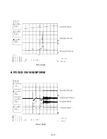
Page 71: ...5 14 8 FOCUS ON WAVEFORM...

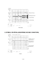
Page 72: ...5 15 9 SPINDLE CONTROL WAVEFORM NO DISC CONDITION...

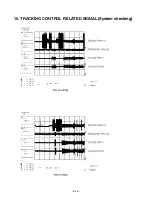
Page 73: ...5 16 10 TRACKING CONTROL RELATED SIGNAL System checking...

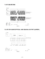
Page 74: ...5 17 11 RF WAVEFORM 12 MT1379 AUDIO OPTICAL AND COAXIAL OUTPUT ASPDIF...

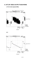
Page 75: ...5 18 13 MT1379 VIDEO OUTPUT WAVEFORM 1 Full colorbar signal CVBS 2 Y...

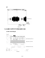
Page 76: ...5 19 3 C 14 AUDIO OUTPUT FORM AUDIO DAC 1 Audio related Signal...

Page 77: ...5 20 MEMO...

Page 78: ...TERMINAL 150M 855 6871RU9271A PWB PCB ASSEMBLY SUBSET AUDIO LHS D6230T FRONT WIRE 5M R CH 856 6871RU9271B PWB PCB ASSEMBLY SUBSET AUDIO LHS D6230T FRONT WIRE 5M L C 857 6871RU9271C PWB PCB ASSEMBLY S...

Page 79: ...ONT FRONT LH 6230WE STANDARD 852 3701RM0043A NET ASSEMBLY SPK LHS D6230W SILVER STANDARD 853 3091RMW050A CABINET ASSEMBLY ASSY LH 6230WE ALL PB 9T 854 6400WTTJ03A SPEAKER WOOFER F65C D365 TOPTONE WOOF...

Page 80: ...2 2 2 3 BLOCK DIAGRAM...

Page 81: ...2 4 2 5 AUDIO SHEMATIC DIAGRAMS U COM SCHEMATIC DIAGRAM...

Page 82: ...2 6 2 7 FUNCTION POWER SCHEMATIC DIAGRAM...

Page 83: ...2 8 2 9 MAIN AMP SCHEMATIC DIAGRAM...

Page 84: ...2 10 2 11 WIRING DIAGRAM...

Page 85: ...KA78R12 1 18 4 18 4 2 12 12 3 0 0 4 5 5 IC706 KIA7805 1 11 11 2 0 0 3 5 5 IC705 KIA7805 1 11 11 2 0 0 3 5 5 D507 D5402 ANODE 0 2 0 2 CATHODE 11 11 D511 D5402 ANODE 0 2 0 2 CATHODE 11 11 BD501 KBU6G 1...

Page 86: ...2 14 2 15 PRINTED CIRCUIT DIAGRAM MAINAMP FRONT P C BOARD SOLDER SIDE...

Page 87: ...2 16 2 17 MAINAMP FRONT P C BOARD COMPONENT SIDE...

Page 88: ...2 18 2 19 FUNCTION POWER P C BOARD SOLDER SIDE...

Page 89: ...2 20 2 21 FUNCTION POWER P C BOARD COMPONENT SIDE...

Page 90: ...3 17 3 18 VCR SHEMATIC DIAGRAMS SYSTEM SCHEMATIC DIAGRAM...

Page 91: ...3 19 3 20 A AUDIO V VIDEO SCHEMATIC DIAGRAM...

Page 92: ...ning Parts that are shaded are critical With respect to risk of fire or electrical shock NOTE 1 Shaded parts are critical for safety Replace only with specified part number 2 Voltages are DC measured...

Page 93: ...3 23 3 24 HIFI TUNER SCHEMATIC DIAGRAM...

Page 94: ...3 25 3 26 A V JACK SCART SCHEMATIC DIAGRAM...

Page 95: ...2 11 2 1 72 1 23 4 76 2 33 40 0 0 0 0 4 6 0 41 0 0 1 0 84 0 83 2 52 2 64 42 0 0 2 15 2 15 2 52 2 61 43 0 0 0 0 2 54 2 65 44 2 1 2 2 4 69 4 67 2 54 2 65 45 2 2 2 2 4 72 4 7 0 57 0 41 46 0 0 2 11 2 94 4...

Page 96: ...3 29 3 30 PRINTED CIRCUIT DIAGRAMS TUNER P C BOARD...

Page 97: ...3 31 3 32 VCR P C BOARD...

Page 98: ...3 33 3 34 VCR P C BOARD...

Page 99: ...5 22 5 21 DVD PART SCHEMATIC DIAGRAMS MPEG SCHEMATIC DIAGRAM...

Page 100: ...5 23 5 24 SERVO SCHEMATIC DIAGRAM...

Page 101: ...5 25 5 26 AUDIO SCHEMATIC DIAGRAM...

Page 102: ...5 27 5 28 INTERFACE SCHEMATIC DIAGRAM...

Page 103: ...5 29 5 30 VOLTAGE SHEET IC TR...

Page 104: ...5 31 5 32 PRINTED CIRCUIT DIAGRAM DVD P C BOARD SOLDER SIDE...

Page 105: ...5 33 5 34 DVD P C BOARD COMPONENT SIDE...

Page 106: ...chanism Exploded View 429 429 026 010 018 013 014 017 015 015A 011 430 431 011A 012 004 001 002 003 A01 A02 020 430 430 430 430 012 021 433 433 012 012 028 022 432 024 A03 A26 025 030 015B 015C 435 02...

Page 107: ...MEMO MEMO...

Page 108: ...A46 285 A47 250 330 276 A42B A42 284 277 267 A43 283 300 320 264 260 321 AUDIO TUNER CABINET AND MAIN FRAME NOTE Refer to SECTION 7 REPLACEMENT PARTS LIST in order to look for the part number of each...

Page 109: ...MEMO MEMO...

Page 110: ...2 1 1 3 Clamp Upper 6 2 2 Tray Disc 6 2 3 Base Assembly Sled 6 3 3 1 Gear Assembly Feed 6 3 3 2 Gear Assembly Middle 6 3 3 3 Gear Assembly Rack 6 3 4 Rubber Rear 6 3 5 Frame Assembly Up Down 6 4 6 Be...

Page 111: ...Rear Frame Assembly Up Down Belt Loading Gear Pulley Gear Loading Guide Up Down PWB Assembly Loading Base Main 2 Screws 2 Locking Tabs 4 Screws 1 Screw 1 Screw 1 Locking Tab 1 Locking Tab 1 Locking T...

Page 112: ...e the Clamp Assembly Disc from the Holder Clamp 1 1 1 Plate Clamp 1 Turn the Plate Clamp to counterclockwise direction and then lift up the Plate Clamp 1 1 2 Magnet Clamp 1 1 3 Clamp Upper 2 Tray Disc...

Page 113: ...CHANISM DISASSEMBLY 3 Base Assembly Sled Fig 6 3 1 Release 4 Screw S2 2 Disconnect the FFC Connector C1 3 1 Gear Assembly Feed 3 2 Gear Middle 3 3 Gear Assembly Rack 1 Release the Scerw S3 4 Rubber Re...

Page 114: ...Unlock the Locking Tab L4 in direction of arrow B and then separate the Gear Pulley from the Base Main 8 Gear Loading Fig 6 4 9 Guide Up Down Fig 6 4 1 Move the Guide Up Down in direction of arrow A a...

Page 115: ......

Page 116: ...C6235 MOLD WAL MART 283 3580R V067A DOOR CASE VCR LH C6235 MOLD WAL MART 284 442 681A SPRING DOOR 285 3580R T101A DOOR CASE DVD LH C6235 MOLD WAL MART 300 6410RAHP02D POWER CORD HIT 110 NISPT 2X18AWG...

Page 117: ...42 CAPACITOR CHIP CERAMIC M L H 1UF 10V Z Y5V F 1508 R TP C260 0CH1105D942 CAPACITOR CHIP CERAMIC M L H 1UF 10V Z Y5V F 1508 R TP C261 0CH1105D942 CAPACITOR CHIP CERAMIC M L H 1UF 10V Z Y5V F 1508 R T...

Page 118: ...OR FIXED CERAMIC Temp 3900PF 50V K Z5U E 1608 R TP C439 0CH1102K562 CAPACITOR FIXED CERAMIC Temp 1000PF 50V 10 X7R X 1608 R T C440 0CH1102K562 CAPACITOR FIXED CERAMIC Temp 1000PF 50V 10 X7R X 1608 R T...

Page 119: ...0CH1104K942 CAPACITOR CHIP CERAMIC M L H 0 1UF 50V Z Y5V F 1508 R TP C536 0CH1102K562 CAPACITOR FIXED CERAMIC Temp 1000PF 50V 10 X7R X 1608 R T C537 0CH1102K562 CAPACITOR FIXED CERAMIC Temp 1000PF 50...

Page 120: ...RC EMC LFA20 2A1E473MT MITSUBISHI MAT L202 6200HJC102A FILTER CIRC EMC HB 1M2012 102JT CERATECH TP L204 6200HJC102A FILTER CIRC EMC HB 1M2012 102JT CERATECH TP L231 6200HJC102A FILTER CIRC EMC HB 1M20...

Page 121: ...TOR METAL GLAZED CHIP 10K OHM 1 16 W 1608 5 00 D R242 0RH2702C622 RESISTOR METAL GLAZED CHIP 27K OHM 1 16 W 1608 5 00 D R243 0RH1002C622 RESISTOR METAL GLAZED CHIP 10K OHM 1 16 W 1608 5 00 D R244 0RH1...

Page 122: ...R457 0RH1003C622 RESISTOR METAL GLAZED CHIP 100K OHM 1 16 W 1608 5 00 D R458 0RH2200C622 RESISTOR METAL GLAZED CHIP 220 OHM 1 16 W 1608 5 00 D R459 0RH2200C622 RESISTOR METAL GLAZED CHIP 220 OHM 1 16...

Page 123: ...5 00 D R535 0RH1001C622 RESISTOR METAL GLAZED CHIP 1K OHM 1 16 W 1608 5 00 D R550 0RH0000C622 RESISTOR METAL GLAZED CHIP 0 OHM 1 16 W 1608 5 00 D R555 0RH0000C622 RESISTOR METAL GLAZED CHIP 0 OHM 1 1...

Page 124: ...CAPACITOR POLYESTER MYLAR 0 1U 100V J POLY TP C209 0CN4730K948 CAPACITOR FIXED TUBULAR High 0 047UF D 50V 80 20 F Y5V C210 0CN4730K948 CAPACITOR FIXED TUBULAR High 0 047UF D 50V 80 20 F Y5V C211 0CN10...

Page 125: ...ROLYTIC 220M SMS 16V M FM5 TP 5 C702 0CE2276F618 CAPACITOR ELECTROLYTIC 220M SMS 16V M FM5 TP 5 C703 0CE4786H650 CAPACITOR ELECTROLYTIC 4700UF SMS 25V M FM7 5 BULK C704 0CE4786H650 CAPACITOR ELECTROLY...

Page 126: ...FILM 560 OHM 1 6 W 5 TA26 R210 0RD5600F608 RESISTOR FIXED CARBON FILM 560 OHM 1 6 W 5 TA26 R211 0RD0102F608 RESISTOR FIXED CARBON FILM 10 OHM 1 6 W 5 TA26 R212 0RD0102F608 RESISTOR FIXED CARBON FILM 1...

Page 127: ...RESISTOR FIXED CARBON FILM 100 OHM 1 6 W 5 TA26 R508 0RD1000F608 RESISTOR FIXED CARBON FILM 100 OHM 1 6 W 5 TA26 R509 0RD1000F608 RESISTOR FIXED CARBON FILM 100 OHM 1 6 W 5 TA26 R510 0RD1000F608 RESI...

Page 128: ...ER DIODE ZD302 0DZ512609BA DIODE ZENER UZ 5 1BSB 26MM TP PYUNG CHANG ZD704 0DZ332609BA DIODE ZENER UZ 33BSB 26MM TP PYUNG CHANG D ZD712 0DZ332609FA DIODE ZENER UZ 3 3BSB 26MM TP PYUNG CHANG VCR MAIN P...

Page 129: ...2 R TP C348 0CH1473K516 CHIP CAPA CERAMIC M L H D F 0 047U 50V K X7R 2 0X1 2 R TP C349 0CH1333K566 CAPACITOR CHIP CERAMIC M L H 0 0330UF 50V K X7R X 2012 R T C350 0CE4764F638 CAPACITOR ELECTROLYTIC 4...

Page 130: ...CAPACITOR FIXED CERAMIC TEMP 0 1UF 2012 50V 80 20 Y5V F C599 0CH1223K516 CAPA CHIP CERAMIC M L H D F 0 022U 50V K B 2 0X1 2 R TP C611 0CE1064F638 CAPACITOR ELECTROLYTIC 10M SRA 16V M FM5 TP 5 C612 0C...

Page 131: ...54K638 CAPACITOR FIXED ELECTROLYTIC 2 2UF SRA SS 50V 20 FM5 TP 5 C880 0CE4754K638 CAPACITOR FIXED ELECTROLYTIC 4 7UF SRA SS 50V 20 FM5 TP 5 C881 0CE1054K638 CAPACITOR ELECTROLYTIC 1 0M SRA SS50V M FM5...

Page 132: ...CHIP 27K OHM 1 10 W 2012 5 00 D R303 0RH1001D622 RESISTOR METAL GLAZED CHIP 1K OHM 1 10 W 2012 5 00 D R304 0RH2201D622 RESISTOR METAL GLAZED CHIP 2 2K OHM 1 10 W 2012 5 00 D R305 0RH5600D622 RESISTOR...

Page 133: ...AZED CHIP 4 7K OHM 1 10 W 2012 5 00 D R536 0RH1001D622 RESISTOR METAL GLAZED CHIP 1K OHM 1 10 W 2012 5 00 D R537 0RH4701D622 RESISTOR METAL GLAZED CHIP 4 7K OHM 1 10 W 2012 5 00 D R538 0RH1001D622 RES...

Page 134: ...0 W 2012 5 00 D R806 0RH7501D622 RESISTOR METAL GLAZED CHIP 7 5K OHM 1 10 W 2012 5 00 D R807 0RH5602D622 RESISTOR METAL GLAZED CHIP 56K OHM 1 10 W 2012 5 00 D R808 0RH2202D622 RESISTOR METAL GLAZED CH...

Page 135: ...ENSO RS501 6500RAB007A SENSOR GP1S566V SHARP REEL SENSOR OF RS502 6500RAB003A SENSOR SG 260 KODENSHI D33 REEL SENSO RS502 6500RAB007A SENSOR GP1S566V SHARP REEL SENSOR OF RESONATOR X301 6202R1357AE RE...

Page 136: ...332609FA DIODE ZENER UZ 3 3BSB 26MM TP PYUNG CHANG D705 0DR154020AA DIODE RECTIFIERS 1N5402 10C BK GULF SEMICONDUCT D706 0DR154020AA DIODE RECTIFIERS 1N5402 10C BK GULF SEMICONDUCT D709 0DR104009AB DI...

Page 137: ...P 0 OHM 1 10 W 2012 5 00 D R605 0RH0000D622 RESISTOR METAL GLAZED CHIP 0 OHM 1 10 W 2012 5 00 D R606 0RH0000D622 RESISTOR METAL GLAZED CHIP 0 OHM 1 10 W 2012 5 00 D R607 0RH0000D622 RESISTOR METAL GLA...

Reviews: