


INSTALLATION INSTRUCTIONS
Zenith Digital Combination Locks
Surface Mounted
Fitting Instructions
The Zenith Digital Combination Lock can be fitted to cupboards,
cabinets and lockers etc as a direct replacement for existing cam
locks or for the Lowe & Fletcher 3751 Digital Combination Lock. It can
also be easily fitted to cupboards and cabinets that do not have an
existing locking device.
Special Notes
Before installing the Zenith Digital Combination Lock, load the
batteries and familiarise yourself with the operation and programming.
Unless manufactured to special order, the lock is supplied in the
“PRIVATE” operating mode.
In this mode, the user must enter a four-digit User Code to open it.
The unit will re-lock itself after four seconds. The lock can be opened
at any time using the Master Code.
Unless manufactured to special order, the default
Master Code is
11 33 55 77
and the default
User Code is 22 44
.
These codes are common to all standard locks and it is very
important that you set your own personal Master and User Codes.
Your lock is not secure until you have changed the default Master
Code and User Code.
Keep a safe record of your master code as it is not possible to make
any programming changes without it.
Please see programming guide to set your own codes.
Installation Guide - IMPORTANT NOTES
The Zenith lock can be fitted with two or three screws. Always use the
screw position “A” behind the logo button. Use either position “B” or
“C” (or both if preferred).
Before drilling fixing holes, please ensure that the position of the
Digital Combination Lock when fitted will allow clearance for selected
cam to work.
ENSURE BATTERIES ARE CORRECTLY FITTED BEFORE FIXING
LOCK
A) New Installation
Step 1
Place template on door and mark TWO 4.5mm (3/16”)
holes (refer to installation diagrams). Use hole position “A”
and either of positions “B” & “C”. Mark ONE 16mm (5/8”)
hole (position “D”).
Step 2
Drill both fixing holes and the 16mm clearance hole.
Step 3
Fit the Digital Combination Lock to the door by passing the
spindle through the 16mm (5/8”) hole.
Step 4
Fit at least two fixing bolts to suit your door thickness.
Step 5
Tighten the upper and lower bolt.
Step 6
Select the cam which suits your door and frame and
attach it to the square shaft at the end of the spindle using
a M4 x 8 screw and domed spring washer.
Step 7
Now check the operation of the lock using the factory
User Code 22 44.
Step 8
If the lock is functioning correctly, CHANGE THE DEFAULT
MASTER CODE 11 33 55 77 and DEFAULT USER CODE
22 44 and program the lock using the programming and
operating instructions enclosed.
B) Replacing existing cam lock with the 378- Digital Combination Lock
Step 1
Remove existing cam lock.
Step 2
Place installation template on door over hole left by cam
lock (position “D”) and mark TWO 4.5mm (3/16”) holes
(refer to installation diagrams). Use hole position “A” and
either of positions “B” & “C”.
Step 3
Drill the two 4.5mm (3/16”) fixing holes.
Step 4
Continue installation from step 3 to 8, above.
C) Replacing existing L&F 3751 Digital Combination Lock with the
378- Digital Combination Lock
Step 1
Remove existing electronic lock.
Step 2
Place installation template on door over the 16mm (5/8”)
hole left by digital lock in position “D” and the 4.5mm hole in
position “A”. Mark ONE additional 4.5mm (3/16”) hole (refer
to installation diagrams). Use either position “B” or “C”.
Step 3
Drill the 4.5mm (3/16”) fixing hole.
Step 4
Continue installation from step 3 to 8, above.
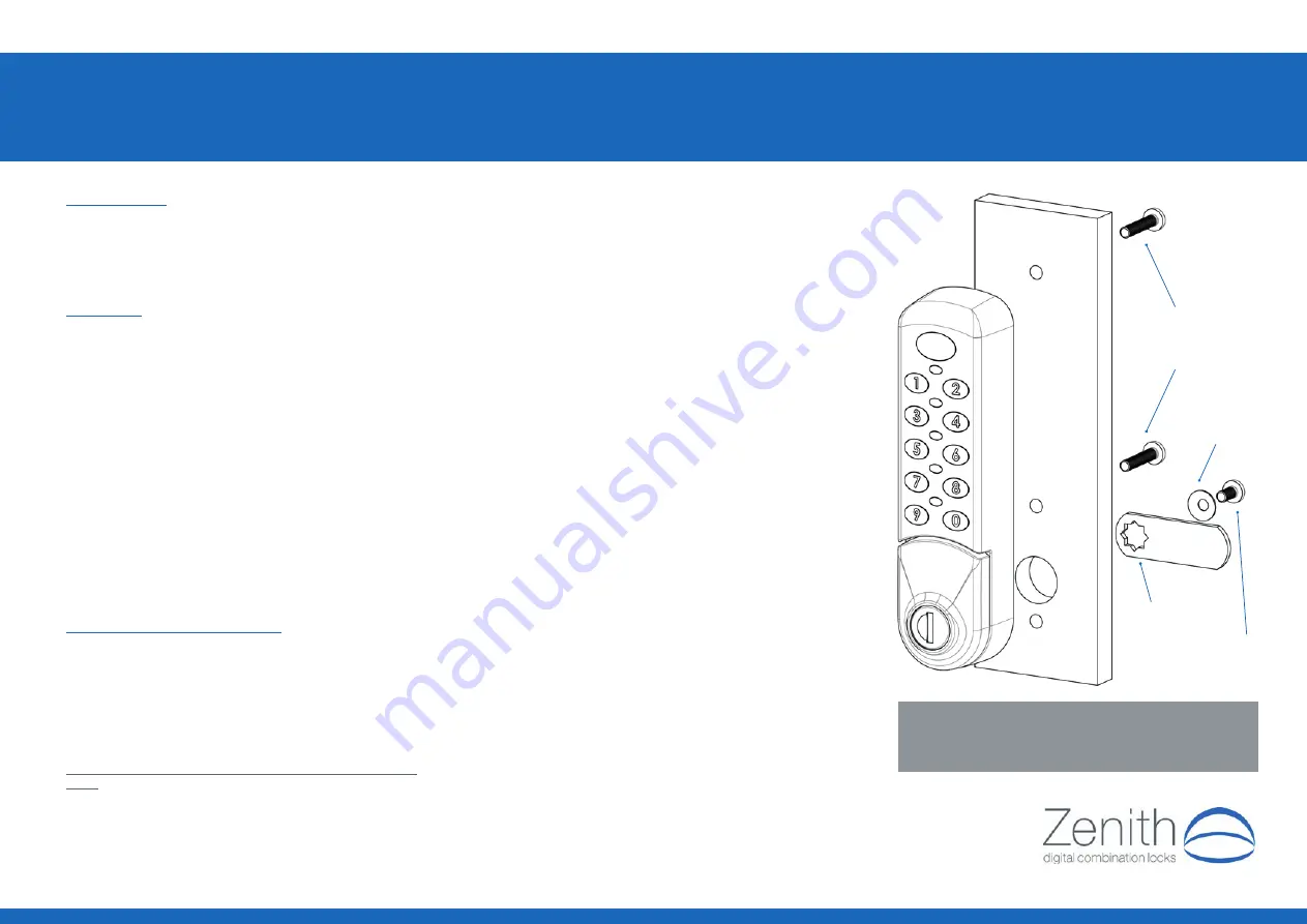
M4 Screws
2 off length to suit
door thickness
M4 Domed
washer
M4 Domed
washer
M4 x 8mm
screw
HOLES A, B & C DIAMETER 4.5 / 5.0mm
HOLE D DIAMETER 16.0 / 16.5mm
ALWAYS
USE FIXING HOLE A AND USE
EITHER
FIXING HOLE
B
OR
C. Recommended screw fixing torque 0.8Nm