


6
should switch to the red LED-indicator
«ON». After charging process is finished
the battery charger will switch off auto-
matically and the «OFF» LED-indicator
will light (the LED-indicator «ON» will
turn off).
NOTE
Remove the battery from the battery char-
ger. As the internal chemical substance of
new batteries and batteries that have not
been used for an extended period is not
activated, the electric discharge may be
low when using them the first and second
time. This is a temporary phenomenon
and normal time required for recharging
will be restored by recharging the batter-
ies 2-3 times.
Charging time may be longer depending
on the surrounding temperature and bat-
tery conditions.
4. Unplug charger from receptacle.
5. Hold the charger firmly and remove
the battery.
how to make Batteries per-
form lonGer
1. Recharge the batteries before they
become completely exhausted. When you
feel that the power of the tool becomes
weaker, stop using the tool and recharge
its battery. If you continue to use the
tool and exhaust the electric current, the
battery may be damaged and its life will
become shorter.
2. Avoid recharging at high temperatures.
A rechargeable battery will be hot im-
mediately after use, its internal chemical
substance will deteriorate, and the battery
life will be shortened. Leave the battery
and recharge it after it has cooled for a
while.
CAUTION
If the battery is recharged when it is
warm due to battery use of exposure
to sunlight, the pilot lamp may light in
green. In such a case, let the battery cool
before charging.
When the pilot lamp flickers rapidly
in red, check and take out any foreign
objects in the charger’s battery installa-
tion hole. If there any foreign objects, it
is probable that the battery or charger is
malfunctioning. Take it to the authorized
service center.
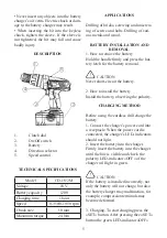
prior to operation
1. Check the area to make sure that it is
clear of debris and clutter.
Check whether working conditions meet
the safety measure.
2.Tightening torque adjustment
• Tightening torque should correspond in
its intensity to the screw diameter. When
too strong power is used, the screw head
may be broken or be injured. Be sure to
adjust the clutch dial position according
to the screw diameter.
• Tightening torque indication. The
tightening torque differs depending on
the type of screw and the material being
tightened. The unit indicates the tighten-
ing torque with the numbers “1,4,7…16”
on the clutch dial, and black dots. The
tightening torque at position “1” is the
weakest and the torque is the strongest at
the highest number.
• Adjusting the tightening torque. Rotate
the clutch and line up the numbers
“1,4,7…16” on the clutch dial, or the dot,
with the triangle mark on the outer body.
Adjust the clutch dial in the weak or the
strongest torque direction according to
the torque you need.
Summary of Contents for CD-18/2 M
Page 1: ...CORDLESS DRILL CD 18 2 M Instruction manual...
Page 2: ......