background image

Preparations for use

OPMI Lumera

®

 i on floor stand  

Version 9.2

Page 82

G-30-1720-en

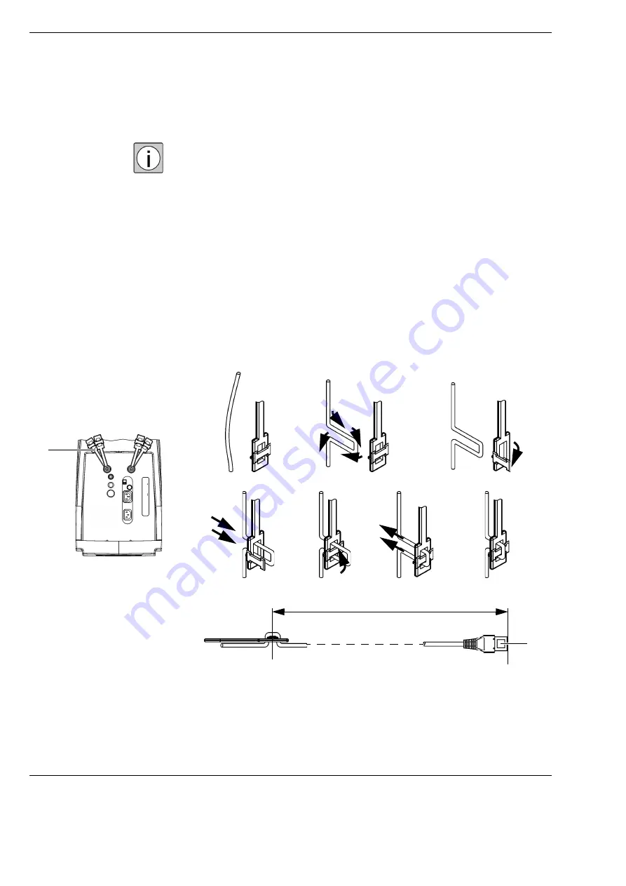
Connecting the strain relief device

Use the strain relief device to prevent the connected cables from being pulled 
out inadvertently.

Make sure that the remaining cable length between the strain relief device 
and the connector (on the connector panel) is approx. 320 mm.

Secure the cable in the strain relief device as follows:

Form a loop with the cable (2).

Open the flap (3).

Feed the cable through the opening (4).

Close the flap (5).

Draw the cable tight until it encloses the flap (6).

Check the cable length.

Fig. 27: Connecting the

strain relief device

1

1

2

3

4

5

6

7

9

320 mm

Summary of Contents for OPMI Lumera i on floor stand

Page 1: ...ZEISS OPMI Lumera i on floor stand Instructions for use G 30 1720 en Version 9 2 2020 10 06 ...

Page 2: ...ions for use apply to OPMI Lumera i with the following identifi cation Reference number 6633 Software release 1 5 1 Trademark OPMI OPMI Lumera Invertertube CALLISTO eye HaMode SCI Stereo Coaxial Illumination MindStream and EDIS are trademarks or registered trademarks of Carl Zeiss Meditec AG or another company of the ZEISS Group in Germany and or other countries Manufacturer s details Subject to c...

Page 3: ...ations 13 Normal use 13 Notes for the operator 15 Duties of the operator 15 Requirements to be met by the user 18 Liability and warranty 18 Requirements for operation 20 Before every use 20 During use 21 After every use 21 Measures to prevent phototoxic injury 22 Illumination characteristics spectral composition 22 Illumination intensity 23 Angle of illumination 23 Focus of the light source 23 Dur...

Page 4: ...ts of the microscope 42 Controls on the microscope 44 Control elements of the tubes 48 Control elements of the widefield eyepieces 49 Components of the stand 50 Control elements on the suspension arm 51 Control elements on the carrier arm stand column stand base 52 Control elements on the lamp housing 53 Connector panel on the floor stand 54 Control elements on the control and display panel 56 Com...

Page 5: ...era 78 Cable connections for the 1Chip HD Camera 79 Connecting system and accessories 80 Connecting the stand to the power supply 80 Connecting the foot control panel to the stand 81 Connecting the strain relief device 82 Connecting video devices option 83 Setting up the system 84 Limiting downward movement of the suspension arm 84 Positioning the device in the OR 85 Adjusting the tilting 86 Adjus...

Page 6: ...ource on off 107 Setting start value of light source 109 Setting magnification 110 Setting start value of zoom system 110 Display of overall magnification 111 Zoom focus link 111 Configuring foot control panel 112 Preconfigured button assignment 112 Changing button assignment 113 System settings 114 Configure XY reset button 114 Configuring parking position 115 Setting speeds 116 Setting parameter...

Page 7: ... control panel 129 Error messages on the 5 7 control panel 129 Care and maintenance System maintenance 132 Maintenance intervals 132 Safety check 133 Changing the halogen lamp 134 Care of the device 136 Cleaning 136 Sterilization 137 Disinfection 137 Environmental protection measures 138 Note on disposal 138 Device data Technical data 140 Essential performance features OPMI Lumera i 140 Accessorie...

Page 8: ...etic immunity for all ME equipment and systems 151 Electromagnetic immunity for ME equipment or systems that are not life sustaining 152 System combinations 153 Accessories and components 154 Components for surgical microscope 155 Other accessories 155 Regulatory information 164 Ambient conditions 165 Indexes Index of technical terms 167 List of abbreviations 167 Index 169 ...

Page 9: ...tions 13 Normal use 13 Notes for the operator 15 Duties of the operator 15 Requirements to be met by the user 18 Liability and warranty 18 Requirements for operation 20 Before every use 20 During use 21 After every use 21 Measures to prevent phototoxic injury 22 Illumination characteristics spectral composition 22 Illumination intensity 23 Angle of illumination 23 Focus of the light source 23 Dura...

Page 10: ... floor stand Safety features 28 Button for backup lamp 28 Filter wheel for protection filter 28 Switch for the manual mode 30 Locking lever for limiting vertical movement 32 Position of the microscope with fundus viewing system 32 Symbols and labels on the device 34 ...

Page 11: ...se note this information and be particularly careful in these cases Information symbols The following information symbols are used in these instructions for use Lists Requirement for an action Prompt for an action Result of an action Additional information and tips These do not contain any warnings of hazards WARNING Indicates a hazard which may lead to severe or fatal injuries if precautions are ...

Page 12: ... ensure that the personnel working with the system possess the necessary qualifications and training Additional service activities are not part of these instructions for use They will be performed by staff specially trained for this purpose by ZEISS Intended field of application Intended use OPMI Lumera i is a surgical microscope intended for the illumination and magnification of the surgical area...

Page 13: ...r and the flexible arms allow the surgeon to adopt an ergonomic position during the operation Preparation After switching on the power button you can move the system safely and smoothly into the working position Intended medical indications for use Medical discipline Ophthalmology Indication OPMI Lumera i is intended exclusively for ophthalmic surgical procedures performed on the eye It illuminate...

Page 14: ... For training purposes or to show employees the steps involved in the surgical workflow a video cable can be connected to the system After surgery Once the surgical procedure is finished the surgeon swings the microscope out of the operating area into the parking position of the suspension arm By pressing the reset button on the XY coupling the system position is initialized to a start value and t...

Page 15: ...ope of its intended use Note the labels attached to the system see page 34 Legal regulations Observe the applicable legal provisions concerning accident prevention and occupational safety in your country If required by the applicable national laws and regulations connect the device to the Special Emergency Power Supply Reporting to manufacturer and authorities If a serious incident occurs in conne...

Page 16: ...lectricity network if you will not be using it for an extended period of time or if you want to clean its surface Switch off the device at the power switch if you notice any smoke sparks or unusual noise Do not use the device until it has been repaired by the ZEISS Service team A potential equalization connector is provided on the instrument s connection panel see IEC 60601 1 This connector can be...

Page 17: ...formed as a minimum for the system Availability of the instructions for use Visual inspection of the device and its accessories for damage as well as legibility of markings and labels Leakage current test Test of protective ground conductor Function and wear test of the brakes Functional check of all switches buttons connectors and indicator lamps on the device Functional test of the manual mode w...

Page 18: ...ce is available for focus positioning Requirements to be met by the user The device may be operated only by properly instructed and trained persons The operator must ensure that the personnel working with the system possess the necessary qualifications and training Keep the instructions for use accessible to the operating personnel at all times Modifications and repairs on this device or any ZEISS...

Page 19: ... monitors have not been calibrated the visualized video sequences video clips and single images may include deviations in scale color and shape Transmission to other monitors in particular may change the display of the images Incorrect data might be used as a basis for subsequent treatment This could lead to unnecessary or incorrect surgery Make sure that stored video sequences video clips single ...

Page 20: ...rd has been plugged into a power outlet which is properly grounded The device is connected with the power cord supplied Before every use Make sure that all functional tests prior to use are performed and the requirements specified above fulfilled Go through the checklist in the section Operation see page 95 Comply with all symbols instructions and labels on the device Never cover any ventilation o...

Page 21: ...osure time of the surgical field to the absolute minimum required Phototoxic effect of light beams When operating on the eye always use the retina protection filter blue barrier filter installed in the light source and or the retina protection cover to ensure that the patient s eye is not exposed to unnecessary blue radiation Adjust the illumination intensity and the resulting radiation exposure t...

Page 22: ... exposing the eye to light with varying spectral compositions have been conducted since the early 1950s These studies suggest that the poten tial hazard of phototoxic injury to the patient s retina can be reduced by blocking out the blue and ultraviolet light proportion below a wavelength of 475 nm Integrated protection filters For protection of the retina ZEISS offers the swing in retina protecti...

Page 23: ...lumination intensity at the patient s eye to the conditions existing in each case Angle of illumination Several publications1 4 suggest tilting the microscope to reduce the exposure of the macula to direct illumination Tilting mechanism The surgical microscope features a tilting mechanism to enable indirect illumi nation Focus of the light source Studies show that injuries are likely to occur if t...

Page 24: ...ture with values ranging from 5 100 The stipulations of standard DIN EN ISO 15004 2 2007 result in maximum radiation exposure times for the different illumination configurations as specified in the table Maximum radiation exposure times see page 26 The maximum brightness of the lamps decreases in the course of time as a result of normal wear Phototoxic risk factors The microscope light source like...

Page 25: ...the field illumi nation to be somewhat darker than the central red reflex spot Not only does this setting minimize the phototoxic risk it also reduces glare reflected from the patient s sclera Other recommendations for minimizing the phototoxic risk are Always use the lowest brightness setting possible Use the retina protective filter blue barrier filter to block the blue spec trum of light The re...

Page 26: ...ues without the blue barrier filter specified below The exact exposure times for the respective illumination values with and without the blue barrier filter can be found in the table below Maximum radiation exposure times Maximum radiation exposure times per light source min sec Without retina protection filter With retina protection filter Halogen 100 brightness 50 brightness 100 brightness 50 br...

Page 27: ...an and A Pollack Microscope induced retinal phototoxicity in cataract surgery of short duration Ophthal mology 109 334 338 2002 5 DIN EN ISO 15004 2 2007 Optical instruments Fundamental require ments and test methods Part 2 Light hazard protection 6 David Sliney Danielle Aron Rosa Francois DeLori Franz Fankhauser Robert Landry Martin Mainster John Marshall Bernard Rassow Bruce Stuck Stephen Trokel...

Page 28: ...o activate the backup lamp Filter wheel for protection filter 2 Filter selector knob for swiveling the protection filter The filter selector knob has four positions No filter Retina protection filter blue barrier filter when operating on the eye always use the retina protection filter to ensure that the patient s eye is not exposed to unnecessary blue radiation KK 40 filter to increase the color t...

Page 29: ...OPMI Lumera i on floor stand Safety measures Version 9 2 G 30 1720 en Page 29 Fig 1 Button for backup lamp and knob for protection filter 1 2 ...

Page 30: ...ss level to permit completion of the application The 5 7 control panel turns black To be able to continue surgery Manually set the magnification on the microscope s zoom adjustment knob 3 1 e g with the help of a coin Manually position the stand for focusing and for moving the system in the XY directions Use an external light source if the light source set to a medium bright ness level is not suff...

Page 31: ...OPMI Lumera i on floor stand Safety measures Version 9 2 G 30 1720 en Page 31 Fig 2 Switch for the manual mode 3 1 3 ...

Page 32: ...ories expressly certified by ZEISS for combination with the surgical microscope described in these instructions for use WARNING Injury to the patient s eye Incorrect operation of the fundus viewing system may cause injury to the patient and impair the image quality Perform the following steps to avoid this hazard Perform a focus reset With the fundus viewing system swung out of the beam path alway...

Page 33: ...OPMI Lumera i on floor stand Safety measures Version 9 2 G 30 1720 en Page 33 Fig 3 Locking lever for limiting vertical movement 4 ...

Page 34: ...ocated between the two arrow tips the focusing system of the microscope is in its initial position Light guide mount This label shows you how to correctly connect the light guide Device name This imprint identifies the system DoF Depth of Field This label identifies the button for the depth of field management system Zoom adjustment knob for manual operation This label identifies the two direction...

Page 35: ...e been mounted on the microscope Radio label FCP Gateway WL optional This device complies with Section 15 of the FCC Rules USA and the RS 210 standard Canada Operation is subject to the following conditions The device does not cause harmful interference The device must remain operative even under the influence of unwanted frequencies Maximum current limitation label The maximum permissible current...

Page 36: ...ce name OPMI Lumera i Rated voltage 115 V 100 125 V 230 V 220 240 V Connected load 115 V max 950 VA 230 V max 950 VA Line frequency range 50 60 Hz Maximum total weight with installed safe workload max 190 kg CSA approval CE marking Information sign Observe disposal regulations Do not dispose of electrical or electronic devices along with normal domestic waste For more infor mation on the disposal ...

Page 37: ...he manufacturer i e phone number fax number and e mail address of the local contact of the national ZEISS sales organization SIP number A unique identification number assigned to your system Warning label Observe transport position Indicates the transport position of the system To avoid any damage to the device always ensure the device is in this position before transporting it Symbol Name Explana...

Page 38: ...Version 9 2 Page 38 G 30 1720 en Safety measures OPMI Lumera i on floor stand ...

Page 39: ...eld eyepieces 49 Components of the stand 50 Control elements on the suspension arm 51 Control elements on the carrier arm stand column stand base 52 Control elements on the lamp housing 53 Connector panel on the floor stand 54 Control elements on the control and display panel 56 Components of the foot control panel 57 Accessories for documentation and co observation 59 EDIS External Data Injection...

Page 40: ...itioned or brought into its parking position suspension arm in upward position The light turns off in the parking position and functions like XY or Focus Reset are reset to their stored start value The downward travel of the suspension arm can be limited as required A maneuvering handle is mounted on the stand column This is used to move the stand and to attach the foot control panel The stand col...

Page 41: ...OPMI Lumera i on floor stand Overview of devices Version 9 2 G 30 1720 en Page 41 Fig 4 System overview 3 1 2 ...

Page 42: ...ope features integrated Stereo Coaxial Illumination SCI for illuminating the surgical field The SCI has been specially designed for the requirements of ophthalmic applications and comprises Red Reflex and surrounding field illumination The Red Reflex illumination provides an optimally visible red reflex and can be controlled using the illumination knob on the microscope For information on how to s...

Page 43: ...OPMI Lumera i on floor stand Overview of devices Version 9 2 G 30 1720 en Page 43 Fig 5 Components of the microscope 2 2 1 4 3 ...

Page 44: ... illumination This is the best setting to generate an optimum red reflex Glare from the sclera is greatly reduced as only the central field of view is illumi nated Position 2 Red Reflex with field illumination This setting permits clear visualization of the red reflex combined with illumination of the surrounding field of view Position 3 Field illumination This setting is used for illuminating the...

Page 45: ...OPMI Lumera i on floor stand Overview of devices Version 9 2 G 30 1720 en Page 45 Fig 6 Control elements on the microscope 2 3 4 1 ...

Page 46: ...are avail able XY Reset Focus Reset always active Zoom Reset The initial value for zoom intensity can be defined via the 5 7 control panel see page 110 Light Reset The initial value for light intensity can be defined via the 5 7 control panel see page 109 Status display of the button Button is not lit the button has been pressed and the system has been reset to the preselected initial status Butto...

Page 47: ...OPMI Lumera i on floor stand Overview of devices Version 9 2 G 30 1720 en Page 47 Fig 7 Control elements on the microscope 9 7 6 5 7 11 10 8 9 ...

Page 48: ... been reached when the two eyepiece images merge into one The set eye distance can be determined with the adjust ment wheel Invertertube 110 tilting tube 3 Eyepiece mount 4 Adjustment wheel for eye distance interpupillary distance 5 Warning symbol Invertertube to be used for main microscope only 6 Adjustment wheel for inverter 7 Symbol for deactivated inverter 8 Symbol for activated inverter Fig 8...

Page 49: ...ents of the eyepieces NOTICE Widefield eyepieces with magnetic coupling When handling eyepieces that have been removed from the tube please keep in mind the usual rules for handling magnets Do not place the eyepiece near instruments which may be magnetizable Do not place the eyepiece on sensitive devices such as infusion pumps pacemakers measuring devices or magnetic data media such as floppy disk...

Page 50: ...he surgical microscope is located in the park position In this position the light turns off and the device is reset to the user specific start values e g XY or Focus Reset see page 115 2 Carrier arm with control panel display 5 7 control panel and connector panel for power supply foot control panel data transfer etc 3 Stand column with supports for cables and foot control panel 4 Stand base with f...

Page 51: ...ical movement for setting the lower limit position see page 84 3 Friction adjustment knob for rotation of the surgical microscope for adjusting the friction of the axis of rotation of the surgical microscope 4 Friction adjustment knob for vertical movement of the suspension arm for adjusting the friction of vertical movement of the suspension arm Fig 11 Control elements on the suspension arm Balan...

Page 52: ...7 control panel 2 Friction adjustment knob for the suspension arm s swivel movement 3 Friction adjustment knob for the carrier arm s swivel movement 4 Cable holder 5 Locking tab for casters 6 Steerable caster 7 Cable deflector 8 Bracket for foot control panel 9 Connector panel 10 Transport handle Fig 12 Control elements on the carrier arm and stand column 2 3 9 1 8 10 5 6 7 4 ...

Page 53: ...icating the operating status of the halogen lamps When the flap is closed the main lamp is operative When the flap is open yellow mark on the side the backup lamp is in use 3 Manual switching to the backup lamp 4 Button for opening the lamp module 5 Button for setting the filter Fig 13 Control elements on the lamp housing No filter Retina protection filter blue barrier filter when operating on the...

Page 54: ... switch for rated voltage The rated voltage displayed here must match the rated voltage of the mains power available at the installation site You can adjust the sliding switch using a suitable tool 6 Power input socket 7 Power output socket for medical devices of max 500 VA CAUTION Danger Electrical voltage Only connect accessories and medical devices designated by ZEISS for use with this system t...

Page 55: ...OPMI Lumera i on floor stand Overview of devices Version 9 2 G 30 1720 en Page 55 Fig 14 Connectors on the floor stand 1 2 5 6 3 4 7 ...

Page 56: ... stand light source and camera if provided and the programmable buttons on the foot control panel 2 Switch for manual mode for manual control of the major functions in the event of system failure see page 30 3 Power switch for switching the device on and off When the device has been switched on the green lamp in the switch is lit The power switch additionally contains an automatic circuit breaker ...

Page 57: ...ordering data Foot control panel with 14 functions wireless FCP WL Foot control panel with 14 functions wired FCP 3 m optional Foot control panel with 14 functions wired FCP 6 m optional Design 1 Connector for connecting the connection cable with the connector panel of the stand 2 Silver colored bracket for storing the foot control panel on the stand Controls Buttons A B C D E F Joystick K The joy...

Page 58: ...ton E light source on off Button F light source on off Joystick The joystick is located between buttons C and D and is used to control the XY coupling Rocker switches The default settings focus zoom of the rocker switches are preconfigured horizontally or vertically for each country However a ZEISS Service technician can change the settings at any time You can make user specific settings your self...

Page 59: ...ctive lenses VOL 442 802 1 VOL 442 video objective lens featuring three optical output ports 2x co observation 1x camera block connection The VOL 802 video objective lens not shown has only one optical output for connecting the camera block 2 Camera block with optical system 3 Stereo co observation module example Only suitable for use with the VOL 442 video objective lens 4 180 tilting tube exampl...

Page 60: ...o camera 2 C Mount adapter for beam splitter video camera connection 3 3 CCD video camera 4 Beam splitter with two optical output ports to which e g a co observation module or a video camera with C Mount adapter can be connected 5 Stereo co observation module example 6 180 tilting tube example Fig 17 Connection via C Mount adapter 2 1 3 6 5 4 ...

Page 61: ...oscopic image of the surgical field The following configurable data can be injected in EDIS TIOL data angle target axis Video recording On Off Assistant functions Incision LRI Rhexis Z ALIGN You will find additional explanations on EDIS in the ZEISS instructions for use EDIS External Data Injection System G 30 1913 Components 1 EDIS module projection unit with integrated data injection and HD came...

Page 62: ...s OPMI Lumera i on floor stand Version 9 2 Page 62 G 30 1720 en 1Chip HD Camera optional 1 The 1Chip HD Camera option is flanged onto a beam splitter 2 The CCU CAMERA CONTROL UNIT control unit for the 1Chip HD Camera 1 2 ...

Page 63: ...Camera option 78 Installing the 1Chip HD Camera 78 Cable connections for the 1Chip HD Camera 79 Connecting system and accessories 80 Connecting the stand to the power supply 80 Connecting the foot control panel to the stand 81 Connecting the strain relief device 82 Connecting video devices option 83 Setting up the system 84 Limiting downward movement of the suspension arm 84 Positioning the device...

Page 64: ...slation takes priority over the above mentioned normative requirements If you have any questions contact your local dealer or ZEISS Service WARNING Risk of serious injury from unauthorized modification You must not modify this device without the permission of the manufacturer The manufacturer is not liable for damage caused by unauthorized persons tampering with the system Unauthorized modificatio...

Page 65: ...OPMI Lumera i on floor stand Preparations for use Version 9 2 G 30 1720 en Page 65 ...

Page 66: ...s and make sure that the stand is no longer able to roll away by itself CAUTION Risk of crushing mind your fingers Fingers may be crushed in the areas marked with the Risk of crushing label Do not touch these areas while the system is being moved or placed into its working transport position CAUTION Mechanical forces can have undesirable impacts when the device is being transported If the followin...

Page 67: ...nderestimate how heavy it is Therefore move the stand slowly and carefully NOTICE Transport over long distances The device may be transported over long distances e g relocation return for repair etc only in its original packaging or in special return packaging For details please contact your authorized dealer or the ZEISS Service team ...

Page 68: ...bed in these instructions for use Never exceed the maximum permissible weight capacity of the suspen sion arm see page 142 Rebalance the suspension arm after every change of equipment see page 77 Tighten all friction knobs firmly WARNING Risk of injury caused by parts falling down Before each use and after re equipping the system make sure that the binocular tube 5 is securely locked into position...

Page 69: ...sary to apply some force Insert the new widefield eyepieces 7 as far as they will go in the mounts 6 intended for them The magnetic coupling reliably secures them in position Unscrew the objective lens 3 from the microscope body by turning it counter clockwise Turn the new objective lens into the threaded mount on the microscope body as far as it will go Loosen the friction adjustment knob 1 again...

Page 70: ... objective lens Connection via a beam splitter and a C Mount adapter see page 74 Mount the beam splitter and the C Mount adapter WARNING Risk of injury caused by accessories falling down Never mount or remove any accessories during surgery Before every use and after re equipping the system make sure that the accessory components are securely locked into position Make sure that all securing screws ...

Page 71: ...ive lens VOL 802 Loosen the locking screw 4 on the video objective lens 5 by a few turns Insert the camera block 1 into the video objective lens 5 in the direction of the arrow as far as it will go Firmly tighten the clamping screw 4 Remove the aperture 3 before performing ophthalmic procedures For this purpose remove the screw 2 Remove the aperture 3 The image brightness is increased The depth of...

Page 72: ...the video objective lens VOL 802 Unscrew the securing screw 4 by a few turns Attach the video objective lens 3 to the surgical microscope 6 The locating screw 5 must fit into the corresponding groove on the video objective lens 3 Firmly tighten the securing screw 4 Fasten the binocular tube 1 in the same way to the video objective lens 3 using the securing screw 2 Fig 21 Mounting VOL 442 video obj...

Page 73: ...er accessories e g camera adapter Loosen the knurled ring 1 on the video objective lens An arrow with the labeling open is located on the shaft next to the knurled ring 1 Remove the dust cover 2 and store it in a safe place Insert the accessory module 3 in the opening of the video objective lens Make sure that the locating blocks fit into the corre sponding grooves of the accessories component 3 S...

Page 74: ... the locating block is fed into the matching part of the knurled ring 4 Screw the knurled ring 4 onto the C Mount video objective lens 2 Firmly tighten the knurled ring 4 Screw the camera head onto the C Mount video objective lens 2 Make sure that the camera image is correctly oriented NOTICE Damage to the camera caused by wrong video lens The maximum screw depth of the C Mount threading of your v...

Page 75: ...OPMI Lumera i on floor stand Preparations for use Version 9 2 G 30 1720 en Page 75 Fig 23 C Mount adapter 3 7 4 2 1 5 8 6 ...

Page 76: ...ion system Insert the correct end of the light guide into the light guide socket 2 of the surgical microscope as far as it will go Always make sure before surgery that both the primary lamp and the backup lamp are intact Fig 24 Connecting the light guide NOTICE Risk of damage to the light guide Please note the label under the light guide socket for the correct connec tion of the light guide 1 Make...

Page 77: ... you think that the spring force is sufficient to compensate for the weight of the surgical microscope and accessories Turn clockwise to increase the spring force turn counter clockwise to reduce it Continue to perform this adjustment until the surgical microscope neither moves upward nor downward The surgical microscope is fully balanced when it remains stationary in all positions within the work...

Page 78: ...e beam splitter with the 1Chip HD Camera remains installed on the surgical microscope If necessary the beam splitter with the 1Chip HD Camera can be removed from the surgical microscope CAUTION Risk of infection due to sagging camera cable If the beam splitter and the permanently connected 1Chip HD Camera are re moved from the surgical microscope and the remaining non sterile camera cable is hangi...

Page 79: ...nt may suffer an electric shock if the video output ports are touched When configuring your system comply with the requirements of IEC 60601 1 IEC 60601 1 1 is still valid in some countries CAUTION Risk of tripping over cables lying on the floor R507 If cables are installed inappropriately on the floor this presents an increased tripping hazard and interferes with the flow of work Users who trip a...

Page 80: ...tage available at the site of installation otherwise the stand will be damaged If the rated voltage has not been correctly set adjust the sliding switch in the indicator window 5 using a suitable tool CAUTION Danger Electrical voltage You may only connect medical devices and accessories designated by ZEISS for this device to the power output socket When using other devices the operator must make s...

Page 81: ...en the device has been switched on the green lamp in the switch is lit Secure the FCP cable with the strain relief device see page 82 Connect the FCP cable to the connector 2 on the stand Fig 26 Connecting the foot control panel NOTICE Use wireless foot control panel Before using the wireless foot control panel FCP WL ensure its batteries are sufficiently charged 2 5 1 3 4 ...

Page 82: ...sure that the remaining cable length between the strain relief device and the connector on the connector panel is approx 320 mm Secure the cable in the strain relief device as follows Form a loop with the cable 2 Open the flap 3 Feed the cable through the opening 4 Close the flap 5 Draw the cable tight until it encloses the flap 6 Check the cable length Fig 27 Connecting the strain relief device 1...

Page 83: ... Video 3 Video output RGB Fig 28 Connecting video devices CAUTION Risk of electric shock caused by inadmissible or defective accessories R506 Unapproved or faulty accessories can cause increased leakage current The user and patient may suffer an electric shock if the signal interfaces or video outputs are touched When configuring your system comply with the requirements of IEC 60601 1 IEC 60601 1 ...

Page 84: ...tion again and check the safety distance The limit of downward travel is only effective in the lower part of the suspension arm s vertical movement range starting from the arm s horizontal position Fig 29 Adjusting the downward travel limit CAUTION Risk of injury caused by lowering of the surgical microscope If the surgical microscope has not been correctly balanced it may lead to downward movemen...

Page 85: ...nvenient for you such as that shown below Make sure that the carrier arm 2 and the suspension arm 4 are not fully extended but are positioned at an angle This provides a greater degree of maneuverability and also a perfect working position Ensure that the device is standing on level ground Press at least two of the locking tabs of the casters 3 and make sure that the stand is no longer able to rol...

Page 86: ...or stand Version 9 2 Page 86 G 30 1720 en Adjusting the tilting Tilt the microscope to the position required The optical axis of the micro scope should generally be positioned at right angles to the patient s eye Fig 31 Adjusting the tilting 1 ...

Page 87: ...iptions of the different users so that they can be easily preset during system preparation Adjusting the interpupillary distance Set the minimum magnification on the main microscope using the foot control panel Position the main microscope above the surgical field Use the knob 1 to adjust the distance of the eyepieces 2 on the binoc ular tube in such a way that the two eyepiece images merge into o...

Page 88: ...be seen Adjusting the magnification Set the maximum magnification on the main microscope using the foot control panel Focus on the object Set the required magnification using the foot control panel The focal plane is retained Eyepieces without reticle Eyepieces with reticle Remove the tube with the eyepieces from the microscope body and point it at a distant object Slowly turn the diopter setting ...

Page 89: ...reparation of resteriliz able products instructions for use for each Asepsis Set For OPMI Lumera i the following Asepsis Caps are available see page 163 for ordering data 1 Asepsis Cap for interpupillary distance adjustment knob 2 Asepsis Caps for handgrips 3 Asepsis Caps for operating buttons Fig 33 Attaching Asepsis Caps CAUTION Risk of infection due to contamination Only use the device with sui...

Page 90: ...n draping the system make sure there is enough slack in the sterile drapes to allow for movement of the microscope carrier and the surgical microscope CAUTION Reduced image quality Drapes with the VisionGuard drape lens may reduce the image quality of the optics Remove the protective film from the drape lens If the drape lens is dirty replace it with a new one ...

Page 91: ...er data 104 Creating new user 104 Selecting users 105 Changing user name 105 Setting language 106 Deleting users 106 Setting light source 107 Switching light source on off 107 Setting start value of light source 109 Setting magnification 110 Setting start value of zoom system 110 Display of overall magnification 111 Zoom focus link 111 Configuring foot control panel 112 Preconfigured button assign...

Page 92: ... 92 G 30 1720 en System settings 114 Configure XY reset button 114 Configuring parking position 115 Setting speeds 116 Setting parameters for overall magnification 117 System information 117 Pairing with wireless foot control panel 117 Typical procedure 119 ...

Page 93: ... start up of the surgical microscope the system displays the default user profile Default User During subsequent log ins the system makes settings for the last user selected The Default User cannot be edited or changed Before using the system you must perform a functional test see next page During this test you can check the device configuration and user specific settings and reconfigure them if n...

Page 94: ...the power switch is no longer illuminated The current of the power outlet socket cannot be switched off by the power switch CAUTION Never leave the device unattended when it is switched on If a patient or an object is exposed to the light source for an extended period of time this can cause burns or fire damage Never leave a device unattended when its light source is switched on ...

Page 95: ...e 116 Check unobstructed movement of the surgical microscope The ease of movement has been adjusted using the friction adjust ment knob on the stand see page 51 All cables and accessories have been installed in such a way that the surgical microscope can be positioned safely without causing any damage CAUTION Failure of functions possible If defects in the device are identified during surgery ther...

Page 96: ...n according to the respective instructions for use Check correct balancing When fully balanced the surgical microscope should remain stationary in all positions within the work area and neither move upward nor downward see page 77 Check downward travel limit The minimum working distance height from the surgical field has been adjusted see page 84 CAUTION Variable light intensity due to a faulty li...

Page 97: ...m The system has been positioned in such a way that it can be moved away from the patient at any time Check foot control panel Stand and surgical microscope must perform the specified functions see page 112 NOTICE Risk of injury when tilting the surgical microscope If the surgical microscope is tilted heavily during an operation the co obser vation tube may swing downward unintentionally or an acc...

Page 98: ...fundus viewing system Incorrect operation of the fundus viewing system may cause injury to the patient and impair the image quality Perform the following steps to avoid this hazard Perform a focus reset With the fundus viewing system swung out of the beam path always position the microscope body in such a way that the index dot 1 of the microscope s focus is in the middle of the upper triangle 2 o...

Page 99: ...OPMI Lumera i on floor stand Operation Version 9 2 G 30 1720 en Page 99 ...

Page 100: ...ed in menus and submenus If a menu option is not selectable the associated button is grayed out The menu name displayed at the bottom right of the screen 8 indicates where you currently are in the menu 1 Main menu 2 User submenu see page 104 3 Magnification submenu see page 112 4 Video submenu no function 5 System settings submenu see page 114 6 Foot control panel submenu see page 112 7 Light sour...

Page 101: ...OPMI Lumera i on floor stand Operation Version 9 2 G 30 1720 en Page 101 Fig 34 Menu structure 2 3 7 6 5 1 8 4 not available ...

Page 102: ...ser blue button changes have been made grayed out button no changes have been made Changing value range You can use the arrow buttons to increase or reduce the numerical values of functions e g light intensity The current value is displayed in the middle When the highest or lowest value has been reached the respective arrow button is grayed out The bar on the left graphically indicates the set val...

Page 103: ...ame is entered in the input field The length of the name is limited to 20 char acters The following input options are available 1 Text field The entered text is displayed here 2 ABC keypad You can use these keys to enter letters 3 Numeric keypad You can use these keys to enter numbers 4 Shift key You can use this key to switch between upper case and lower case letters 5 Space key You can use this ...

Page 104: ... save the user A menu is displayed asking you to confirm the assignment of data Tap on the Yes button to assign the current user data to the user or the No button to assign the default data to the user The user is saved The User menu is displayed again To assign a specific profile to the new user change the respective menu settings If necessary select the required language in the Choose Language f...

Page 105: ...from the user list Press the button to load the user A menu is displayed asking you to confirm the assignment of data The user specific language is set The User menu is displayed again Changing user name Press the User button in the main menu The User menu is displayed Select the user to be edited in the Choose User field The Default User cannot be edited Press the Edit button The Edit menu is dis...

Page 106: ...ton to save the change Data transfer information is displayed The language setting is changed The Main menu is displayed again Deleting users Press the User button in the main menu The User menu is displayed Select the user to be deleted in the Choose User field The Default User cannot be deleted Press the Delete User button A menu is displayed asking you to confirm your selection Tap on Yes to co...

Page 107: ...e Light On Off button The light source is on when the button lights up in dark blue CAUTION Damage to the eye caused by high light intensity Too much light intensity brightness or excessive radiation exposure times may lead to retinal injury in the patient s eye Adjust the illumination intensity as required for the selected type of illu mination and the radiation exposure time You will find the va...

Page 108: ...0 1720 en If a different user logs in the current status of the light source is retained When the system is rebooted the light source is reset to its Light Off default status To save the changes press the button The setting is saved The Main menu is displayed again ...

Page 109: ...activated see page 114 Set the device to its parking position if the function is activated see page 115 Press the Light button in the main menu The Light menu is displayed Adjust the light intensity start value in the range from 5 to 100 Press the button to increase the light intensity and the button to reduce it The selected light intensity is displayed as a percentage value between the two butto...

Page 110: ...device on Press the reset button if the function is activated see page 114 Set the device to its parking position if the function is activated see page 115 Press the Magnification button in the main menu The Magnification menu is displayed Set the start value for the zoom system in the range from 0 4 to 2 4 Press the button under Zoom value to increase the start value and the button to reduce it T...

Page 111: ...iece the parameters need to be readjusted accordingly Zoom focus link This function permits the focusing speed to be coupled with the current zoom value to facilitate focusing on object details The preselected focusing speed is automatically reduced when a higher magnification is used Press the Magnification button in the main menu The Magnification menu is displayed Press the Zoom speed linked bu...

Page 112: ...econfigured but they can be reassigned to meet the user s specific requirements The factory settings are Button A light intensity Button B light intensity Button C no function Button D no function Button E switch light source on off Button F switch light source on off Joystick The joystick located between the buttons C and D is used to control the XY coupling Rocker switches The default settings f...

Page 113: ... want to change A list of the selectable functions is displayed If several selectable func tions are available a scroll bar is displayed Use the arrow buttons to scroll up and down Tap on the function to be assigned to the button Repeat these two steps until you have assigned the required functions to all buttons or rocker switches of the foot control panel To save the changes press the button The...

Page 114: ... start values when the XY reset button 1 is pressed The settings are saved for the specific user Select System Settings XY Reset in the main menu The submenu XY Reset is displayed CAUTION Risk of collision Pressing the reset button 1 moves the XY coupling into its configured starting position and or moves the focus into the center position This may cause injury to the patient or damage to mounted ...

Page 115: ...enu is displayed again Configuring parking position The parking position is reached when the suspension arm 1 is moved to the topmost position This automatically switches the light off The functions are reset to their stored start values depending on the settings made Proceed as follows for user specific settings Select System Settings Park Position in the main menu The Reset Park Position menu is...

Page 116: ...Settings button in the main menu The System Settings menu is displayed Press the Speeds button The Speeds menu is displayed It includes the following functions Focus speed Press the button to increase the focus speed and the button to reduce it XY speed Press the button to increase the XY speed and the button to reduce it Zoom speed Press the button to increase the zoom speed and the button to red...

Page 117: ... again System information The Versions submenu permits you to check the software currently installed on your system Press System Settings System Options Versions in the main menu The Versions menu is displayed It contains information about the PC software PC SW and firmware Light OPMI XY Camera Gateway Foot Panel currently installed Pairing with wireless foot control panel Pairing refers to the fi...

Page 118: ...iring If pairing was successful the Radio link intensity status indicator 1 flashes green for approx 1 s and the following message appears Pairing successfully completed Bring the foot control panel in a hori zontal position working position and perform a function test Set the wheel of the foot control panel to the number indicated on the suspension system You can check whether pairing was success...

Page 119: ...ad to retinal damage in the patient s eye Adjust the illumination intensity and the resulting radiation exposure time by selecting the appropriate illumination setting You will find the values recommended by ZEISS in the Maximum radiation exposure times table on page 26 When operating on the eye use the retina protection filter blue barrier filter It protects the patient s eye against unnecessary ...

Page 120: ...in injury to the anterior eye segment To prevent contact with the patient ensure that the range of movement is sufficient for the position of the focus WARNING Risk of injury due to vertical movement of the suspension arm If the suspension arm is adjusted the stand can move vertically causing the surgical microscope to come into contact with the patient This can result in serious injuries to the p...

Page 121: ...s may lead to retinal damage in the patient s eye Never leave a device unattended when its light source is switched on NOTICE Restricted functions due to malfunctioning motor electronics If the motor electronics malfunction major functions such as XY movement focus zoom or light control may be impaired Activate the manual mode see page 125 Move the microscope manually into the required position Se...

Page 122: ...Operation OPMI Lumera i on floor stand Version 9 2 Page 122 G 30 1720 en ...

Page 123: ... Page 123 What to do in the event of malfunctions Failure of the halogen light source 124 Failure of a main function XY focus zoom light 125 Troubleshooting 126 For your safety 126 System malfunctions 126 Malfunctions of the FCP foot control panel 129 Error messages on the 5 7 control panel 129 ...

Page 124: ...ion is defective the backup lamp can also be swiveled in manually Press the button 3 to manually swivel the backup lamp into the beam path Replace the defective lamp at the first opportunity see page 134 If the backup lamp is defective and replacement is not possible continue surgery using an external OR illuminator Fig 35 Swiveling in the backup lamp NOTICE Lamp module overheating If ventilation ...

Page 125: ... the manual mode to complete a surgical procedure that has already been started for example Press button 1 to switch to the manual mode Working in the manual mode In the manual mode the light source is set to a medium intensity and XY coupling focus drive and zoom system are switched off Manually move the microscope in the X and Y directions for positioning Manually move the microscope up and down...

Page 126: ...rom the chap ter What to do in the event of malfunctions attach a sign Out of order to the system and inform ZEISS Service System malfunctions Malfunction Possible cause Remedy Reference No function at all Power plug of stand not inserted Plug in the power cord Page 80 Power switch of stand not switched on Press power switch Green indicator light in the power switch must be lit Page 93 Automatic c...

Page 127: ...ghtness on stand or foot control panel Page 107 Lamp ageing may lead to reduced light intensity Replace lamp Page 134 Defective light guide illumination not uniform Replace the light guide Contact ZEISS Service Light guide not correctly inserted Check that the light guide is connected Page 76 Filter selection knob is in an intermediate position Turn knob until filter is correctly in place Page 53 ...

Page 128: ...evel of noise Use of a camera adapter Remove fixed stop from camera adapter Instruc tions for use for camera Activate the integral light metering function of the camera to reduce reflec tions from the sclera and cornea Instruc tions for use for camera Increase the brightness level of illumination Page 107 Motor driven focusing and or zoom functions of surgical microscope are inoperative Failure of...

Page 129: ... for your country on the following website www meditec zeiss com Malfunction Possible cause Remedy Reference Foot control panel is inoperative Connections on stand or foot control panel not plugged in Plug in connections Page 81 Error message Possible cause Remedy Reference XY coupling error The error can be acknowledged If the error impairs your work please switch to the manual mode and contact Z...

Page 130: ...ual mode and contact ZEISS Service e g jammed motor of the focus system If the error impairs your work switch to the manual mode Page 125 System boot error Please reboot the system Please make sure that no function buttons are pressed during the booting process e g a button was pressed during system start Reboot the system Make sure not to press any buttons during this process System error The err...

Page 131: ...30 1720 en Page 131 Care and maintenance System maintenance 132 Maintenance intervals 132 Safety check 133 Changing the halogen lamp 134 Care of the device 136 Cleaning 136 Sterilization 137 Disinfection 137 Environmental protection measures 138 Note on disposal 138 ...

Page 132: ...owing sections describe the procedures to follow for performing main tenance tasks yourself Any other maintenance activities that are not described here in detail require device specific knowledge Please contact your local ZEISS Service or an authorized partner in a timely manner to have these maintenance tasks carried out Interval Maintenance work Every 2 years Visual inspection and function test...

Page 133: ... of the instructions for use Visual inspection of the device and its accessories for damage as well as legibility of markings and labels Leakage current test Test of protective ground conductor Function and wear test of the steerable casters and locking tabs Functional check of all switches buttons connectors and indicator lamps on the device Function test of manual mode without the patient at lea...

Page 134: ...he interior of the reflector 6 Press the halogen lamp into the spring loaded mount 4 5 Push the lamp module including the new halogen lamp back into the device Turn on the device with the power switch 3 Instructions for use sign Observe the instructions for use or further applicable documents 9 CAUTION warning label Warning of a potential hazard Follow the instructions to change the lamp NOTICE 10...

Page 135: ... i on floor stand Care and maintenance Version 9 2 G 30 1720 en Page 135 Always make sure before surgery that both the primary lamp and backup lamp are intact Fig 37 Changing the halogen lamp 6 7 5 8 4 9 10 1 3 2 ...

Page 136: ...ing a squeeze blower or a clean grease free brush For regular cleaning of the surgical microscope s objective lenses and eyepieces we recommend using the optics cleaning kit available from ZEISS For the catalog number please see the section Device data Ordering data Fogging of optical surfaces We recommend using an anti fogging agent to protect the eyepiece optics from fogging Anti fogging agents ...

Page 137: ...croscope In order to ensure that the lamps are able to cool sufficiently and to avoid any loss in lamp functionality take care not to cover the ventilation slots Disinfection It may be necessary to disinfect the surfaces The maximum concentrations for application are For alcohol tested with 2 propanol 60 For aldehyde tested with glutaraldehyde 2 For quaternary compounds tested with DDAC 0 2 NOTICE...

Page 138: ...ided by the manufacturer on the Internet Where the product or its components are resold the seller must inform the buyer that the product must be disposed of in accordance with the currently applicable national regulations For customers in the European Union If you wish to dispose of electrical or electronic devices please contact the dealer or supplier Information on disposal in countries outside...

Page 139: ... compatibility 148 EMC Electromagnetic compatibility IEC 60601 1 2 2014 4th edition 150 Electromagnetic interference 150 Electromagnetic immunity for all ME equipment and systems 151 Electromagnetic immunity for ME equipment or systems that are not life sustaining 152 System combinations 153 Accessories and components 154 Components for surgical microscope 155 Other accessories 155 Regulatory info...

Page 140: ...s defined by the manufacturer have been tested The following device functions have been defined for the immunity test Visualization of the object must be maintained minor image distortions are permitted The lighting for object illumination must be maintained interruptions of less than one minute are permitted The zoom must be adjustable Focusing must be possible Operation via the foot control pane...

Page 141: ...e XY reset button is pressed the focusing drive moves to the starting position of the focusing range Focal length of objective lens f 200 mm f 175 mm option f 225 mm with support ring option Tubes eyepieces 180 tiltable tube f 170 mm Inclined tube f 170 mm option Invertertube option 10x widefield eyepieces with magnetic coupling 12 5x widefield eyepieces with magnetic coupling option Swivel filter...

Page 142: ...microscope Approx 8 5 kg without tube objective lens and eyepieces Suspension arm Length 750 mm Swivel angle 290 Lifting range 400 mm 320 mm Carrier arm Length 450 mm Swivel angle 360 Stand height 1730 mm Base dimensions 640 x 640 mm Maximum permissible load of suspension arm When the surgical microscope without tube eyepieces objective lens and the XY coupling have been mounted the weight of addi...

Page 143: ...OPMI Lumera i on floor stand Device data Version 9 2 G 30 1720 en Page 143 Fig 38 Dimensional drawing of OPMI Lumera i ...

Page 144: ...tomatic fuse Electrical outputs Wall outlet 115 230 V max 500 VA Video output RGB Video output Y C Video output BNC Remote socket for an external signal with max 24 V 0 5 A Fiber optic illumination Lamp housing with 2 halogen reflector lamps 1 backup lamp with 12 V 100 W in quick change modules for one light guide Retina protection filter blue barrier filter and KK 40 filter to increase the color ...

Page 145: ...ng system 2 1 interlace 625 lines 50 fields second 25 frames second Analog video output ports FBAS VBS 1 0 Vp p 75 Ω PAL composite Y C 1 0 Vp p 75 Ω luminance 0 3 Vp p 75 Ω chroma Component Feature Image sensor 1 2 inch interline transfer CCD image sensors with 768 H x 494 V pixels Horizontal resolution 480 lines at 768 pixels Signal to noise ratio 50 dB with Y C signal Scanning system 2 1 interla...

Page 146: ...interlace scan CCD image sensors Horizontal resolution 800 lines Vertical resolution In accordance with PAL standard Signal to noise ratio 62 dB Scanning system Interlace 50 fields second Analog video output ports FBAS VBS 1 0 Vp p 75 Ω PAL composite Y C 1 0 Vp p 75 Ω luminance 0 3 Vp p 75 Ω chroma RGB 0 7 Vp p 75 Ω for R G B 0 3 Vp p 75 Ω synchronization composite sync ...

Page 147: ...ntal resolution 800 lines Vertical resolution In accordance with NTSC standard Signal to noise ratio 62 dB Scanning system Interlace 60 fields second Analog video output ports FBAS VBS 1 0 Vp p 75 Ω PAL composite Y C 1 0 Vp p 75 Ω luminance 0 286 Vp p 75 Ω chroma RGB 0 7 Vp p 75 Ω for R G B 0 3 Vp p 75 Ω synchronization synchronization sync Component Feature Transmission frequency 2402 2480 MHz Re...

Page 148: ...on Do not install or operate OPMI Lumera i in close proximity to other devices with the exception of the device combinations described in these instruc tions for use as this can impair the functioning of OPMI Lumera i If operation of OPMI Lumera i in the proximity of other devices is unavoidable OPMI Lumera i must be monitored for proper functioning WARNING Function deterioration Electrical device...

Page 149: ... represent a potential risk of improper functioning of medical devices Malfunctions may be caused by a variety of local factors These cannot be predicted or estimated in any way Please follow the EMC guidelines on the following pages NOTICE Danger from electromagnetic radiation OPMI Lumera i may experience interference from other devices even if these other devices comply with the emission require...

Page 150: ...an electromagnetic environment as specified below The customer or the user of OPMI Lumera i is responsible for ensuring that the device is operated in such an environment Measurements of interference emissions Compliance HF emissions as per CISPR 11 Group 1 HF emissions as per CISPR 11 Class B Harmonic emissions as per IEC 61000 3 2 Class A Emission of voltage fluctuation flicker as per IEC 61000 ...

Page 151: ...bursts as per IEC 61000 4 4 2 kV for power lines 2 kV for power lines 1 kV for input output lines 1 kV for input output lines Surge voltages surges as per IEC 61000 4 5 0 5 kV 1 kV phase neutral voltage 0 5 kV 1 kV phase neutral voltage 0 5 kV 1 kV 2 kV phase neutral to ground voltage 0 5 kV 1 kV 2 kV phase neutral to ground voltage Power frequency 50 60 Hz magnetic field as per IEC 61000 4 8 30 A...

Page 152: ... operated in such an environment Immunity tests IEC 60601 test level Compliance level Conducted HF disturbances as per IEC 61000 4 6 3 V 150 kHz to 80 MHz 3V 6 V ISM frequency bands from 150 kHz to 80 MHz SIP SOPs tested with lengths 3 m 6V Radiated HF disturbances as per IEC 61000 4 3 3 V m 80 2700 MHz 3 V m Radiated HF disturbances from near fields of wireless commu nication devices as per IEC 6...

Page 153: ...Do not connect any additional power strips Only connect compatible components to the system Do not exceed the maximum permissible electrical load of power strips Use power strips only for components of the system Medical electrical systems Any additional equipment you connect to medical electrical devices must demonstrably comply with the applicable standards and directives e g IEC 60950 1 for dat...

Page 154: ...basic components The other compo nents for the respective function are evident from the descriptive text For this reason you should also cite the descriptive text in any orders Ordering data for OPMI Lumera i surgical microscope Ordering data for country specific cables for floor stand Description Order number OPMI Lumera i on floor stand system 305946 9900 000 Dust cover blue with ZEISS logo 0000...

Page 155: ...on 000000 1023 188 Description Order number 180 tiltable tube 303791 0000 000 Inclined tube with 45 viewing angle option 303784 0000 000 Invertertube option 303797 9120 000 Description Order number Objective lens f 200 mm 302652 9904 000 Objective lens f 175 mm option 302651 9902 000 Objective lens f 175 mm with support ring option 302671 9902 000 Objective lens f 200 mm with support ring option 3...

Page 156: ... with inverter tube and 10x eyepieces Stereo co observation module with 2 pivot joints 000000 1063 869 Inverter tube 303797 9120 000 Widefield push in eyepiece 10x 305542 0000 000 Stereo co observation module complete with inclined tube and 12 5x eyepieces Stereo co observation module with 2 pivot joints 000000 1063 869 Inclined binocular tube f 170 mm 45 degrees 303784 0000 000 12 5x push in wide...

Page 157: ...x 305542 0000 000 Sleeve for tubes with screw thread 305542 0107 000 Assistant s microscope 8 complete Assistant s microscope 8 f 200 mm 302624 9901 000 3 step magnification changer 303429 9903 000 Inclined binocular tube f 170 mm 45 degrees 303784 0000 000 Sleeve for tubes with screw thread 305542 0107 000 12 5x push in widefield eyepiece asph 305543 9901 000 Assistant s microscope 0 complete Ass...

Page 158: ...681 8767 000 Beam splitters for the 1Chip HD Camera Splitter 20 beam splitter 20 301503 9901 000 With the 1Chip HD Camera option for OPMI Lumera i you automatically receive the 1Chip HD Camera instructions for use G 30 1946 Description Order number Monitors external Sony 21 full HD monitor 308203 9430 000 NDS 24 HDTV monitor with 5 m HD SDI video cable and stand base NDS 24 HDTV monitor Base for 2...

Page 159: ... Mini DIN 000000 0300 281 10 m S VHS connection cable 2 x 4 pin Mini DIN sturdy and gold plated contacts 308203 3070 000 HD SDI video cable 75 Ohm 2xBNC pin 5 m 305989 8763 000 HD SDI video cable 75 Ohm 2xBNC pin 10 m 305989 8764 000 HD SDI video cable 75 Ohm 2xBNC pin 15 m 302681 8766 000 Component HD YPbPr cable 10 m 308203 3080 000 TRIO 610 extension cable 4 m 308203 2400 000 Country specific p...

Page 160: ...amera instructions for use G 30 1946 UC foot control panel for zoom and focus S7 foot control panel for zoom and focus UC foot control panel connector 305946 9200 000 000000 1237 540 Description Order number Wireless foot control panel Foot control panel with 14 functions wireless FCP WL Back up for wireless foot control panel 3 m cable for foot control panel with 14 functions FCP FCP WL 6 m cable...

Page 161: ... 000 Adapter for connecting older generation FCP Adapter for connecting an older generation FCP FCP2 to Lumera i and LUMERA 700 305946 8185 500 Description Order number RESIGHT 500 manual focusing unit 302721 9020 000 Description Order number EDIS consisting of EDIS module with integrated HD camera EDIS box CCU 302755 9004 000 EDIS cable set consisting of EDIS Box cable set 10 m for EDIS module ED...

Page 162: ...K Switzerland Argentina China Brazil 000000 0301 997 000000 0147 000 000000 0400 264 309850 9011 000 000000 0434 527 000000 0475 507 000000 0527 730 Description Order number Halogen lamp 12 V 100 W 380079 9040 000 Optics cleaning kit 000000 1216 071 Disposable plastic gloves large size 8 9 000000 0117 736 Disposable plastic gloves medium size 7 8 000000 0117 737 Description Order number ...

Page 163: ...ope with straight tube 6 caps per pack 305810 9006 000 Asepsis Caps VISULUX rubber caps for VISULUX 2 caps per pack 305810 9009 000 Asepsis Caps for handgrips resterilizable rubber caps for handgrips of the main microscope 6 caps per pack 305810 9010 000 Drapes sterile disposable drapes OPMI Drapes sterile type 70 ZEISS VisionGuard Drapes for surgical microscopes with 2 observation tubes and camer...

Page 164: ...on of the devices according to IEC 60601 1 The device is classified as follows Degree of protection against electric shock Class 1 Degree of protection against ingress of water IP X0 Electromagnetic compatibility EMV Fulfills the standard IEC 60601 1 2 Class B as per CISPR 11 Operating mode continuous operation ...

Page 165: ...For transport and storage Feature Admissible range Temperature 10 C 40 C Rel humidity 30 75 Atmospheric pressure 700 hPa 1060 hPa Feature Admissible range Temperature Without 1Chip HD Camera With 1Chip HD Camera 25 C 60 C 20 C 60 C Rel humidity without condensation 10 90 Atmospheric pressure 500 hPa 1060 hPa ...

Page 166: ...Version 9 2 Page 166 G 30 1720 en Device data OPMI Lumera i on floor stand ...

Page 167: ...rrects the orientation of the image by using the fundus viewing system or wide angle optics Depth of field Range of depth that appears sharply defined through the microscope Radiation intensity Radiation incident or emitted at right angles per time unit and area Taring Balance between input and output Term Explanation AG Aktien Gesellschaft incorporated company BNC Bayonet Neill Concelmann coaxial...

Page 168: ...association for certification of management systems EMC Electromagnetic compatibility describes the non interference of electrical and electronic devices with their environment EN European Norm FCC Federal Communications Commission USA FCP Foot Control Panel RF Radio Frequency ICC Information and Control Center IEC International Electrotechnical Commission IOL Intraocular lens artificial lens for ...

Page 169: ...t control panel 52 Button assignment on foot control panel preconfigured 58 C Cable connections 79 Cable connections for 1Chip HD Camera 79 Cable holder 52 CALLISTO eye on roll stand 61 Care 131 Carrier arm 50 CCU camera control unit 61 Change tubes eyepieces or objective lens 68 Changing the halogen lamp 134 Characteristics of illumination 22 Cleaning 136 Cleaning optical surfaces 136 Components ...

Page 170: ...trol panel 102 Carrier arm 52 Control and display panel 56 Lamp housing 53 Microscope 44 Suspension arm 51 Controls Tubes 48 Widefield eyepieces 49 D DeepView depth of field management system 44 Depth of field management system DeepView 44 Diagnostic purposes 19 Diopters Scale 49 Setting ring 49 Disinfection 137 Display 5 7 control panel 56 Focusing range 46 Rated voltage 54 Display overall magnif...

Page 171: ...53 Retina protection filter 28 Selection knob 53 Fire hazard 21 First start up 93 Foot control panel 40 Button assignment 58 Components 57 Configure 112 Connect 81 Malfunctions 129 Pairing 117 Friction adjustment knob for surgical microscope 51 for the carrier arm s swivel movement 52 for the suspension arm s swivel movement 52 for vertical movement of suspension arm 51 Functional test 95 H Hand g...

Page 172: ...ver for limiting vertical movement 51 Locking tab 52 M Main microscope 42 Maintenance 131 Malfunctions Error messages on the 5 7 control panel 129 Foot control panel 129 System 126 Maneuvering handle for positioning the floor stand 52 Manual mode 125 Switch 30 56 Manual switching to the backup lamp 53 Manufacturer s address 2 Max radiation exposure times with red reflex illumination 26 Medical ele...

Page 173: ...eters for overall magnification 117 Perform balance setting 77 Position device in OR 85 Power on off 93 Power switch 56 Preparations for use 63 Prepare for sterile use 89 Procedure 119 Protective ground connector 20 R Rated voltage 144 Relocating the device 66 Reset 46 Reticle 88 Retina protection filter 28 S Safety Devices 28 Inspection 133 Safety measures 9 SCI illumination 42 Set magnification ...

Page 174: ...l mode 30 56 Power switch 56 Sliding switch for rated voltage 54 Switch for the manual mode 30 Symbols and labels on the device 34 System Overview 40 Remedying malfunctions 126 System combinations 153 System settings 114 Configure parking position 115 Configure XY reset button 114 Pairing with wireless foot control panel 117 Set overall magnification 117 Set speeds 116 System information 117 T Tar...

Page 175: ...05 Create 104 Delete 106 Manage data 104 Select 105 Set language 106 V Video accessories 158 Virtual keyboard 103 W What to do in the event of malfunctions 123 Working in manual mode 125 X XY Configure reset button 114 Coupling 40 Z Zoom emergency operation 44 Zoom focus link 111 ...

Page 176: ...Version 9 2 Page 176 G 30 1720 en OPMI Lumera i on floor stand ...

Page 177: ...OPMI Lumera i on floor stand Version 9 2 G 30 1720 en Page 177 Blank page for your notes ...

Page 178: ...Carl Zeiss Meditec AG Goeschwitzer Strasse 51 52 07745 Jena Germany E mail info meditec zeiss com Internet www zeiss com med ...

Reviews: