10 Troubleshooting
Instructions for Use
OPMI LUMERA 700
10.4 Troubleshooting work
198 / 236
G-30-1673-en - 14.0 - 2018-07-12
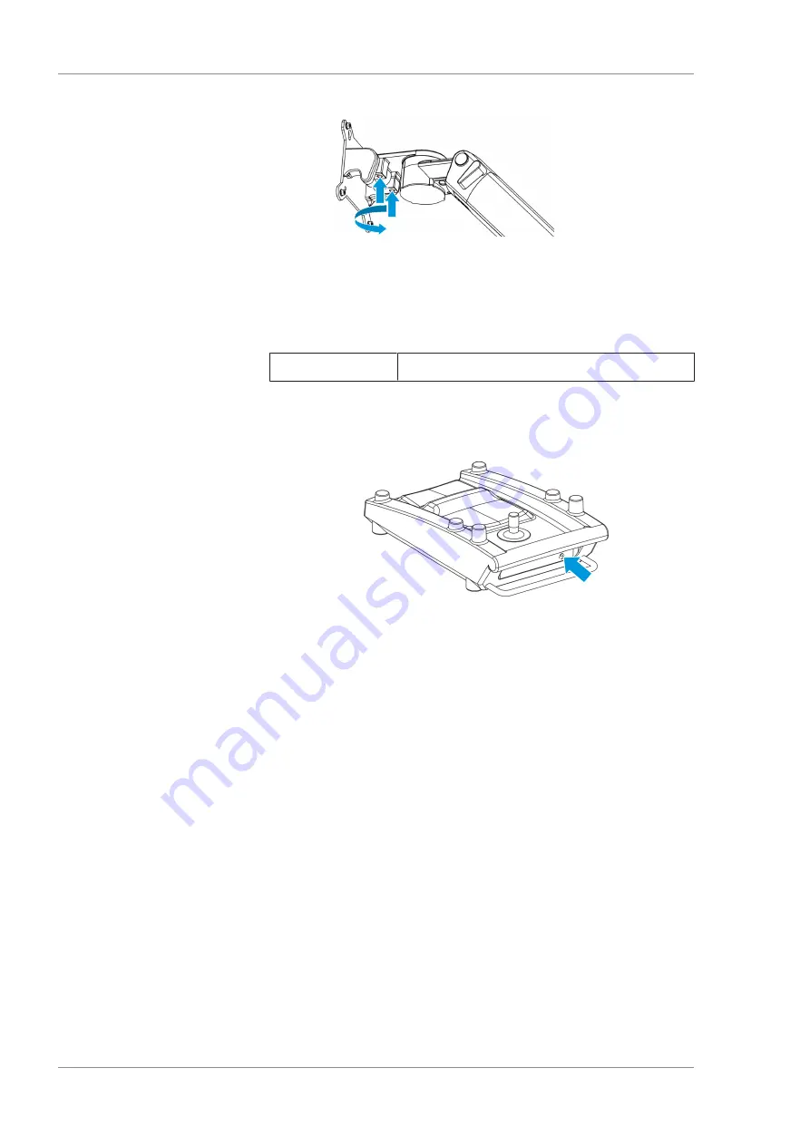
10.4.10 Establishing cable connections for the 14-function foot
control panel
If the 14-function foot control panel continues to be non-opera-
tional after pairing, connect it to the device using a cable.
Material
• 3m, 6m or 10m cable
Prerequisite
þ
The power switch is off.
Action
1. Insert the 6-pin connector into the socket on the 14-function
foot control panel.
2. Insert the 4-pin connector (straight or angled) into the socket
on the stand.
10.4.11 Displaying the firmware versions
An overview of the installed firmware versions is available in the
"Versions" menu. The information displayed varies depending on
the equipment the device is outfitted with.
Action
1. Open the main menu.
2. Tap the [System Settings] menu button.
3. Tap the [Versions] button.
ð
The "Versions" menu will appear.
4. To view all firmware versions: tap the arrow buttons.
ð
The menu will scroll up or down.
10.4.12 Opening the service menu
The service menu is password-protected and may only be accessed
by personnel trained by ZEISS.
Prerequisite
þ
The service PIN is available
Action
1. Open the main menu.
Summary of Contents for opmi lumera 700
Page 1: ...OPMI LUMERA 700 Software Release 3 1 Instructions for Use...
Page 10: ...Empty page for your notes...
Page 14: ...Empty page for your notes...
Page 30: ...Empty page for your notes...
Page 130: ...Empty page for your notes...
Page 200: ...Empty page for your notes...
Page 222: ...Empty page for your notes...
Page 226: ...Empty page for your notes...
Page 230: ...Empty page for your notes...
Page 235: ...Empty page for your notes...


