background image

54

Corona process  |  User Manual

Maintenance

Corona process

11 

Calibration of the spare lamp

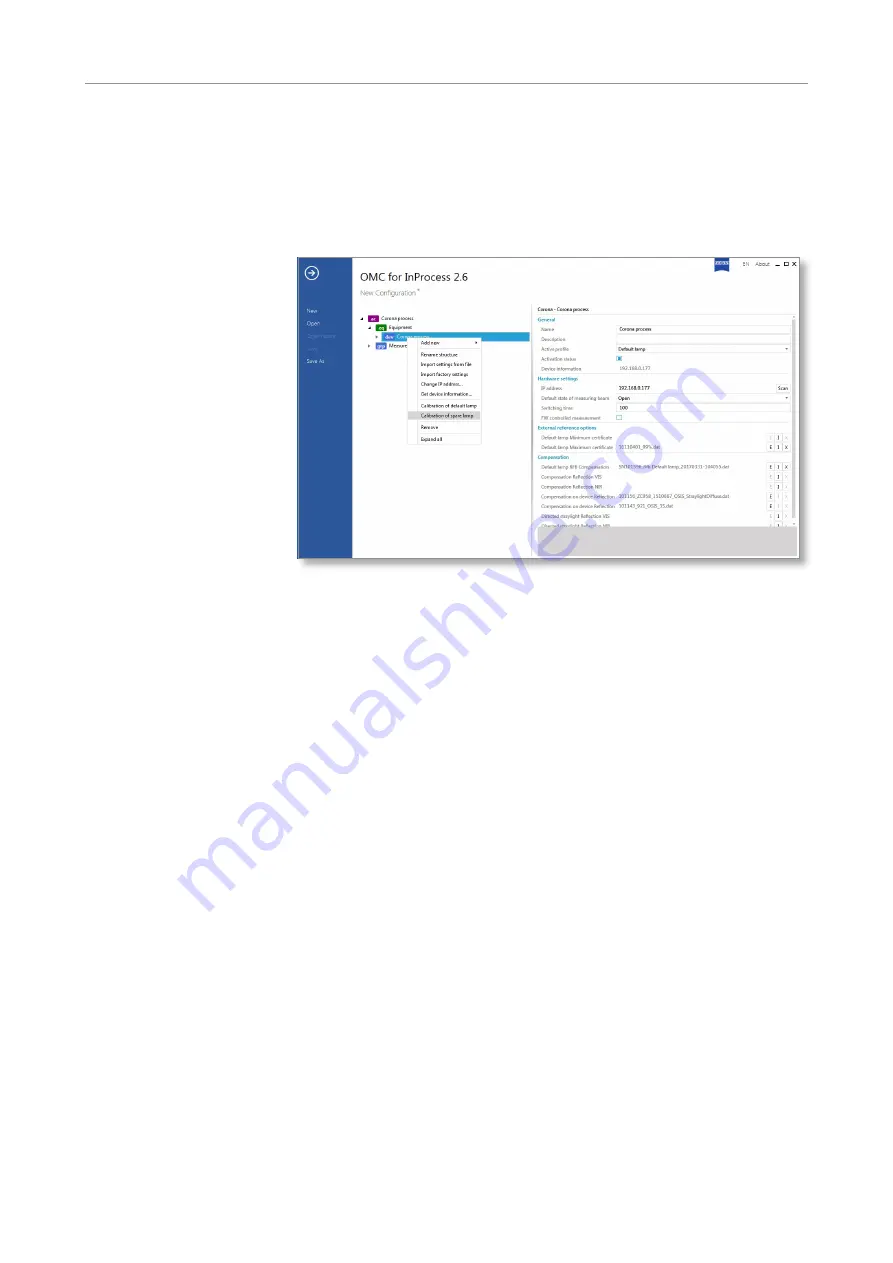
Now calibrate the spare lamp by right-clicking on 

dev Corona process

 and 

selecting 

Calibration of spare lamp

.

Fig. 40  Selecting a spare lamp

Repeat steps 4 to 10 for the spare lamp.

The 

Corona process

 measuring system is again ready for operation.

Final measures

Summary of Contents for Corona process

Page 1: ...User Manual Carl Zeiss Spectroscopy GmbH Corona process...

Page 2: ...d forwarding and duplication of this document and the utilization and communication of its contents are not permitted Violations shall result in claims for damages All rights reserved in the event of...

Page 3: ...3 3 1 Scope of supply 13 3 2 Technical design 14 3 2 1 Functional elements 14 3 2 2 Controls and indicators 15 3 2 3 Electrical connections 16 3 2 4 Mechanical interface 17 3 3 Functional description...

Page 4: ...ting device and the Corona process 23 Fig 9 Connecting system components 25 Fig 10 Selecting the storage location and agreeing to the licensing terms 26 Fig 11 Completing the installation 26 Fig 12 Se...

Page 5: ...49 Fig 33 Confirming the alignment 49 Fig 34 Positioning the white standard 50 Fig 35 Continuing the white calibration 50 Fig 36 Positioning the black standard 51 Fig 37 Continuing the black calibrat...

Page 6: ...6 Corona process User Manual Corona process...

Page 7: ...ffectively Furthermore it will provide you with information on maintenance and troubleshooting Please familiarize youself with the contents of the User Manual and observe all of the general and safety...

Page 8: ...afety note could result in slight injuries or property damage Note General reference to important or useful information concerning the device and its operation Note Important note on environmental pro...

Page 9: ...ctives and standards and left our factory in perfect condition To maintain this state and ensure safe operation all instructions and warning notes listed must be observed The following directives stan...

Page 10: ...ve atmosphere Unplug the power connector of the device only when the device is deenergized Caution GENERAL RISK The Corona process including its original accessories must be used for the purposes desc...

Page 11: ...in compliance with the applicable legal requirements 2 4 Environmental management Our company has implemented a certified environmental management system that complies with ISO 14001 This product was...

Page 12: ...particular and improper use The manufacturer shall not be liable for damage caused by faulty operation negligence or any other tampering with the device particularly the removal or replacement of dev...

Page 13: ...e f e r s c h e i n Corona extreme Gebrauchsanweisung 2 1 3 4 5 7 8 6 Scope of supply Corona process spectrometer Acceptance report Delivery note and other documents accompanying the device Set of doc...

Page 14: ...ig 2 6 1 5 2 4 3 7 Functional elements Connection panel Ethernet Digital IN OUT power supply and status display Cooling element Carrying handle and mounting interface Device base carrier for the measu...

Page 15: ...color Description flashing blue after connection to the power supply not lit during initialization max 30 s no light beam visible in measuring window flashing blue after complete initialization no lig...

Page 16: ...l IN OUT connection 10 pin socket PIN Color Assignment 1 bk wh OUT 3 2 violet IN 0 3 brown OUT 2 4 white IN 1 5 green OUT 1 6 yellow IN 2 7 gray OUT 0 8 pink IN 3 9 blue GND 10 red GND 12 24 V DC POWE...

Page 17: ...Corona process with optional mounting device in mounting package 000000 2107 066 from Carl Zeiss Spectroscopy GmbH see also Section 4 Variant 2 Fastening of the Corona process via a customer installed...

Page 18: ...h two redundant halogen lamps and automatically switches over to the second lamp if the first one fails The stainless steel housing and the hygiene standard adhered to the design allow the use of the...

Page 19: ...cess 1 2 3 4 5 6 90 600 mm Functional description Mounting device in mounting package 000000 2107 066 or customer installed mechanical interface Mounting interface handle Corona process measuring syst...

Page 20: ...ftware manual is available on the attached CD The Corona process measuring system is approved for use with the following software packages InProcess Aspect Plus The OSIS SDK Software Development Kit 0...

Page 21: ...10 to 50 C Storage transport tempera ture 40 to 70 C Max humidity 95 non condensing Altitude of operation Up to 2000 m Tab 2 Connection and environmental conditions 4 If you do not use the original m...

Page 22: ...face with four M8 threaded holes or four through holes with a diameter of 9 mm for fastening the mounting device For the connection dimensions of the mounting device please refer to the illustration b...

Page 23: ...orona process with the carrying handle 5 in the location holes 4 of the mounting device At the same time note the transport direction of the sample material see note 4 Align the Corona process properl...

Page 24: ...e Ethernet cable must be less than 100 m max 80 m is recommended or a switch must be interposed To prevent communication problems the use of a second network card for the Corona process is recommended...

Page 25: ...alling the measuring system Corona process Fig 9 2 3 1 2 1 Connecting system components ETHERNET connection Digital IN OUT connection Protective cap only for Digital IN OUT connection POWER 12 24 V DC...

Page 26: ...luded on the CD ROM for InProcess Software 1 Start the installation process by double clicking on the setup exe file 2 Select the storage location and agree to the licensing terms 3 Then click on INST...

Page 27: ...Process software you still must activate the required licenses Note For details on activation of the required licenses please refer to the ZEISS License Activation Manual As soon as you have activated...

Page 28: ...28 Corona process User Manual Corona process...

Page 29: ...booted up completely the Status LED flashes blue in one second intervals blue flashing after connection to the power supply not illuminated during initialization max 30 s no light beam is visible in t...

Page 30: ...a process default lamp is set as the default profile For details on changing the profile refer to the technical description Information on the device profiles of the Corona extreme and Corona process...

Page 31: ...t and assign a product name to it by clicking on 7 Then select Continuous measurement Fig 14 Select continuous measurement 8 Save the product To do this click on the Save button Fig 15 Save product No...

Page 32: ...al System Operation Corona process 9 Return to the start screen by clicking on the Home button 10 Click on the Measurement button 11 Start a measurement by clicking on the button for the desired produ...

Page 33: ...nge to the spare lamp and replace the default lamp if necessary only by instructed personnel Switch measuring system off and on Restart software Signal strength too weak Distance between sample and me...

Page 34: ...34 Corona process User Manual Help in case of faults Corona process Error Cause Remedy Other errors questions and maintenance work Contact customer service...

Page 35: ...clean it Caution THERMAL ENERGY HAZARD Let the Corona process measuring system cool down for at least 10 minutes before starting to clean it Follow the safety instructions for handling inflammable liq...

Page 36: ...ply by third parties Caution GENERAL RISK All specified activities may be performed only by Service staff of Carl Zeiss Spectroscopy GmbH or by properly instructed personnel Caution THERMAL ENERGY HAZ...

Page 37: ...belonging to the calibration device for the Corona process Phillips screwdriver PH2 for older device versions Open end wrench 8 mm A F Screwdrivers TX10 and TX25 Additionally required tools and acces...

Page 38: ...ess 2 Removing the Corona process from the mounting device Loosen both clamping screws 1 on the mounting device using a 6 mm Allen screw Pull the Corona process 2 out of the mounting device Fig 18 2 1...

Page 39: ...Loosen Phillips screws with a PH2 Phillips screwdriver Carefully lift the base of the device 2 by the carrying handle 3 out of the device cover 4 Make sure that you do not feel any resistance while d...

Page 40: ...nel the default lamp L1 is located on the left side of the device base and the spare lamp L2 is on the right side The corresponding labeling also is affixed to the lamp base Note The procedure for cha...

Page 41: ...t it will not obstruct further work steps or be damaged Fig 21 1 Disconnecting the lamp cable 6 Unscrewing the lamp holder Unscrew three of the four screws 2 from the lamp base with a TX25 screwdriver...

Page 42: ...ables run over the lamp holder of the spare lamp Therefore remove the lamp holder of the spare lamp by taking it out at the side Fig 23 2 1 Removing the lamp holder 8 Removing the old halogen lamp Pla...

Page 43: ...ogen lamp 9 Installing the new halogen lamp see Fig 24 reverse order Put on the cotton gloves Insert the new halogen lamp 4 in the lamp holder 5 Align the new halogen lamp so that the black mark on th...

Page 44: ...s see Fig 25 4 1 Screw the lamp holder back onto the base with the four screws see Fig 22 2 Plug the lamp cable see Fig 21 1 back onto the lamp socket 11 Inserting the device base in the device cover...

Page 45: ...white standard with appropriate certificate attached CD Black standard Tools for changing lamps Corresponding instructions Storage box Ethernet cable order no 000000 2036 573 Lab power supply order no...

Page 46: ...uring system has not yet been configured select it for configuration under the menu option New Fig 27 Selecting a measuring system 3 Selecting the lamp to be calibrated Right click on dev Corona proce...

Page 47: ...tenance Corona process Note The program sequence must be performed completely for the default lamp and for the spare lamp 4 Resetting the lamp counter Reset the lamp counter by pressing the Yes button...

Page 48: ...the attached CD which is supplied in a folder in the storage case Compare the report number on the white standard with the one on the CD and select the appropriate csv file Fig 30 Determining the whi...

Page 49: ...se cover with the supplied cover We recommend that you certify the white standard annually Insert the white standard in the standard holder at position P6 Fig 32 Mounting the white standard Adjust the...

Page 50: ...axis 1 against the measuring window 4 of the Corona process until it touches the measuring window Fig 34 4 3 2 1 5 Positioning the white standard Fasten the white standard 3 in this position by tighte...

Page 51: ...ing of the white standard and remove the standard holder from position P1 Replace the white standard with the black standard and position the standard holder in position P2 Fig 36 Positioning the blac...

Page 52: ...e white standard again fits closely against the measuring window and fix it in this position with the clamping screw see Fig 34 Fig 38 Continuing the distance correction Press the OK button to continu...

Page 53: ...the distance correction The calibration of the default lamp has been completed successfully and the correction has been saved under the following link C ProgramData ZEISS OSIS Device Fig 39 Saving th...

Page 54: ...the spare lamp Now calibrate the spare lamp by right clicking on dev Corona process and selecting Calibration of spare lamp Fig 40 Selecting a spare lamp Repeat steps 4 to 10 for the spare lamp The C...

Page 55: ...m 000000 2102 398 Ethernet cable for Corona 10 m 000000 2119 388 Ethernet cable for Corona 15 m 000000 2058 862 Ethernet cable for Corona 60 m 000000 2146 834 RJ45 connector with insulated ends 000000...

Page 56: ...able 10 pin 000000 0547 289 Cover cap for Digital IN OUT socket 000000 0583 776 Accessories Flushing rings Name Order number ClearView flange 000000 2164 968 Air purge ring 000000 2192 999 Accessories...

Page 57: ...utton with connecting cable 5 m 000000 2186 146 Accessories TURNSTEP Name Order number TURNSTEP 000000 2156 193 TURNSTEP adapter for petri dishes 60 mm 000000 0455 055 TURNSTEP adapter for petri dishe...

Page 58: ...e but should be disposed of in compliance with the relevant legal requirements This product has been developed inspected and produced in accordance with the applicable environmental regulations and di...

Page 59: ...ers Dimensions W x H x D 360 x 279 x 220 mm Weight 15 0 kg Ambient parameters Operating temperature 10 C to 50 C Storage transport temperature 40 C to 70 C Protection class IP67 ATEX Zone 22 Max humid...

Page 60: ...al range 380 1650 nm Spectral resolution half tenth value width 10 nm Wavelength accuracy 1 0 nm Wavelength drift 10 pm K Geometry 0 0 Min integration time 3 ms Amplitude digitization 16 bits Measurin...

Reviews: