


zebris Medical GmbH
FDM-T Technical Data and Operating Instructions
Page 22/65
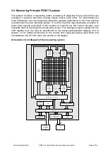
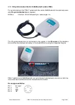
3.5
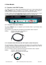
Controls and Connectors
All the cable connections are carried out via the interface box which is located on the un-
derneath of the treadmill frame on the back, on the right-hand.
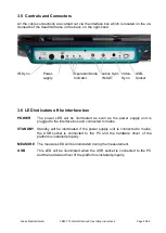
3.6
LED indicators oft he interface box
POWER
The power LED will be illuminated as soon as the power supply unit is
plugged to the interface box and connected to mains.
STANDBY
Standby will be illuminated if the power supply unit is connected to mains,
the USB socket is connected to the PC and the hardware driver of the
platform is installed properly.
MEASURE
The measure LED will be illuminated during the measurement.
USB
This LED will be illuminated when the USB socket is connected to the PC
and the hardware driver of the platform is installed properly.
USB-
Socket
Power-
supply
IR-Sync.
zebris Sync
IN/OUT
Operation Mode
Indicator
Video-
Sync.