background image

To ensure failure-free operation of the SYNCLights, it is mandatory 
to keep the black heat sinks at their back side uncovered and well 
air circulated at all times.

The Sync-LEDs are fl ashing when the camera is disconnected from 
the USB port. Therefore, it is strongly advised not to look directly into 
the camera when it is disconnected to avoid dazzling.

Seite 29/69

Seite 29/41

FDM-T-Sports

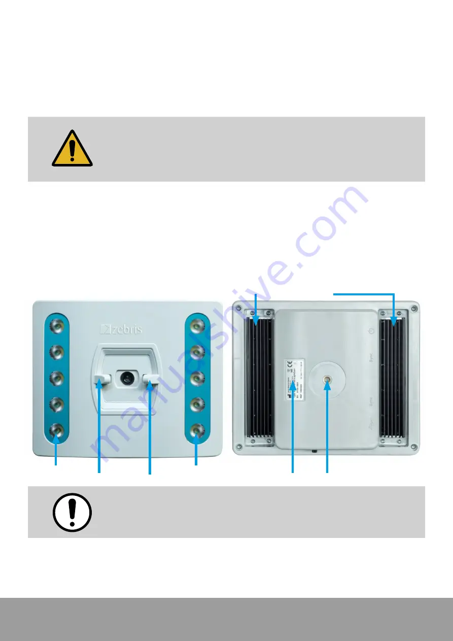
4.4 SYNCLightCam – variant 30 Hz 

The SYNCLightCam is an accessory of the FDM-T system and perfectly adapted to be used in 
combination with the pressure distribution measurement. All adjustments of the camera are 
carried out via hardware setup integrated to the zebris FDM software. The camera is connected 
to the PC by a USB cable of type A-B included within the shipment. 
The SYNCLightCam is equipped with ¼ inch tripod threads and can be adapted to zebris tripods 
as wells as commercially available camera tripods.

Furthermore, contains the SYNCLightCam as an integral solution, the LED video illumination. 
To produce well lighted and tack sharp video captures it is essential to maintain perfect lighting 
conditions at the patient’s side. Only with adequate lighting conditions video cameras can work 
with shutter times short enough to freeze fast movements and capture sharp images. 
This solution is perfectly matched on the interaction with the FDM-T system and can be regulated 
infi nitely in its brightness. 
The integrated synchronization unit automatically switches the lights on at the start of a measurement 
and turns them off again after stopping it.

¼ inch tripod thread

Flash LEDs

Power LEDs

Power LEDs

Typeplate

Heat sink

Summary of Contents for FDM-T-Sports

Page 1: ...FDM T Sports Operating Instructions and Specifications...

Page 2: ...edical GmbH Textrelease R 1 Stand 30 08 2021 REF Nr 79010094 Manufacturer zebris Medical GmbH Phone 49 0 7562 9726 300 Am Galgenbu hl 14 Fax 49 0 7562 9726 50 D 88316 Isny im Allg u Email sales zebris...

Page 3: ...ensor 3 3 Technical Specifications FDM T measuring systems 3 4 Measuring principle FDM T system 3 5 Controls and connectors 3 6 LED indicator lights of the interface box 3 7 zebris SYNC 3 7 1 Synchron...

Page 4: ...mendations for recording data 5 7 1 Treadmill analysis 5 7 2 Data recording 5 7 3 Walking speed 5 7 4 Posture 5 7 5 Weals 6 Maintenance and safety inspections 6 1 General maintenance procedures 6 2 Ma...

Page 5: ...nsors and treadmill can also be used completely independently of each other and feature a separate power supply and CE mark The user manual for the FDM T measuring system therefore consists of several...

Page 6: ...azard that can result in dam age of the device The notes explain the type of hazard and how it can be prevented This symbol indicates a potential hazard that can cause a loss of eyesight This warning...

Page 7: ...dically used rooms or oxygen enriched atmospheres The devices must not be operated in proximity to e g engines or transformers with a high connected load as well as mains current lines as electrical o...

Page 8: ...s delivered by zebris responsibility is assumed if Assembly extensions resettings changes or repairs were carried out through zebris or third parties authorised by zebris trained technicians or employ...

Page 9: ...of fault or doubt If any fluids should penetrate the device it is mandatory for the device to undergo a technical safety test Damaged plug connections and leads are to be replaced by an authorized ser...

Page 10: ...Make sure that if a person trips over their long hair loose clothing jewellery etc do not encounter the rear part of the treadmill belt e g wear a hair net Due to danger of stumbling do not place any...

Page 11: ...plications using wheels are prohibited cycling wheelchair inline skating or roll ski as well as running shoes with spikes or studs Besides their extremely high risk of injury these can cause irreparab...

Page 12: ...M software 3 2 Specifications FDM T sensor The sensors of the different FDM T systems only vary in size of the measuring area the number of single sensors included in the sensor module and the support...

Page 13: ...sions L x W x H 160 x 80 4 x 136 cm folded 160 x 80 4 x 28 cm Step height 18 cm Incline adjustment manually 2 steps Max user weight 120 kg Colour white black Measuring range 1 120 N cm Sampling rate 1...

Page 14: ...x 88 kg Dimensions L x W x H 177 x 69 x 115 cm Step height 16 cm Incline adjustment 0 to 15 in 1 steps Max user weight 120 kg Colour black green Measuring range 1 120 N cm Sampling rate 100 Hz Sensor...

Page 15: ...16 cm Incline adjustment 0 to 15 in 1 steps Max user weight 150 kg Colour black green Measuring range 1 120 N cm 1 120 N cm Sampling rate 100 Hz 120 Hz optional 240 Hz Sensor area 94 8 x 40 6 cm 108...

Page 16: ...L x W x H 188 x 70 x 142 cm Step height 20 cm Incline adjustment 3 bis 19 0 to 22 Max user weight 150 kg Colour white Measuring range 1 120 N cm Sampling rate 120 Hz Sensor area 91 x 39 cm Number of...

Page 17: ...rted is determined for each individual sensor To do this the drive logic generates several sinus burst signals equivalent to the number of columns via the column decoder and transmits them to the resp...

Page 18: ...to the interface box and connected to mains STANDBY Lights up if the power supply unit is connected to mains the USB socket is con nected to the PC and the hardware driver of the platform is installe...

Page 19: ...to 5V 1 by an internal pullup resistor 2 7 k If this input is set to 0 V 0 i e by a switch or break contact than the SYNC IN is triggered Electrical spezifications Input Resistance Pull Up 5V 2 7 k V...

Page 20: ...of the third party device either via start stop or sample by sample mode Electrical specifications Input Resistance Pull Up 5V 100 V VIH High Level Input Voltage 2 0 V VIL Low Level Input Voltage 0 8...

Page 21: ...treadmill 21030071 USB2 0 cable A B Data connection between interface box and PC length 3 m 07200010 zebris FDM Software for operating system Windows 10 64 Bit 79010094 Hardware User Manual The print...

Page 22: ...e or infrared includes software extension 01540194 SYNCLightCam 30 Hz Combined solution with Camera and illumination 5 m USB2 0 Cable synchronization cable inclusive software extension 01831105 SYNCLi...

Page 23: ...Modul virtual training Software extension interactive treadmill training on a virtual forest path contains levels with different levels of difficulty and an additional level Acoustic Cueing 01530100 O...

Page 24: ...ta the camera must be connected to the galvanically isolated Viodeosync socket on the interface box Videosync and USB socket at the backside of the tradmill PDM C sensor 4 1 1 Connection to the zebris...

Page 25: ...r supply Mascot 0813105 Power supply Mascot 9926 SYNCLightCam 1 21030071 USB cable A B 21030320 SYNCCam USB cable A B 01830041 Videosync control cable 2 5 21030312 Videosync control extension 01830041...

Page 26: ...sure distribution measurement All adjustments of the camera are carried out via hardware setup integrated to the zebris FDM Software The camera is connected to the PC by a USB cable of type A B includ...

Page 27: ...nt All adjustments of the camera are carried out via hardware setup integrated to the zebris FDM software The camera is connected to the PC by a USB cable of type A C included within the shipment The...

Page 28: ...ization with special synchronization cable included in the scope of delivery Infrared Synchronization via infrared signal without synchronization cable not compatible with every zebris pressure plate...

Page 29: ...a USB cable of type A B included within the shipment The SYNCLightCam is equipped with inch tripod threads and can be adapted to zebris tripods as wells as commercially available camera tripods Furthe...

Page 30: ...DM T Sports Technical specifications REF 01540194 Variant 30 Hz Dimensions 220 x 183 x 80 mm B x W x T Weight ca 790 g Power supply 24 V 36 W Resolution 1920 x 1080 Pixel Full HD Autofocus Frame Rate...

Page 31: ...which results in reduced brightness to prevent the LEDs from being damaged by excessive heat Power supply unit For operation of the SYNCLight plus a power supply unit needs to be connected REF 331022...

Page 32: ...nd 1 m in width must be kept free directly behind the treadmill No items may be left in this zone video camera etc For setup installation and safety related instructions of the treadmill please refer...

Page 33: ...acteristics Connect only if they are compatible For operating the FDM T sensor exclusively use the power adapter approved by zebris which is suitable for the power supply of all FDM T systems Seite 33...

Page 34: ...of the treadmill and the FDM T power supply unit must be done at a separate wall socket It is not permissible to use extension cables and or multiple sockets Seite 34 69 Seite 34 41 FDM T Sports 5 2...

Page 35: ...tuation 5 7 1 Treadmill analysis Walking on the treadmill is unfamiliar to most people and takes a certain time to get used to it It is therefore of advantage to familiarize the test person with this...

Page 36: ...e sliding surface underneath the treadmill belt is no longer sufficiently lubricated g A malfunction or a defect is suspected or has been detected Check regularly approx every 25 operating hours wheth...

Page 37: ...s Before each use of the measuring system it is recommended for safety reasons to check the correct state of all the connection cables as well as the mains cable mains plug and mains socket Should cer...

Page 38: ...e shown for a condition without any load In addition the pressure distribution images are to be checked regularly for untypical measuring patterns These include above all line or column shaped measuri...

Page 39: ...d to the PC and the device driver is correctly installed Are all the other components of the measuring system infrared synchronization with zebris video camera connected correctly Check list for notin...

Page 40: ...disinfectant s recommended duration of impact Please make sure to switch off the device and pull the mains plug out of the socket before you commence disinfecting and cleaning Do not use any aggressiv...

Page 41: ...e the measuring system can be returned to zebris Medical GmbH at the end of its service life at the customer s own expense and will be forwarded to special recycling companies without any further cost...

Reviews: