background image

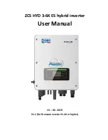
ZCS HYD 3-6K ES hybrid inverter 

User Manual 


13 – 06 - 2019 

V1.1 (for firmware version V1.40 or higher) 


Summary of Contents for HYD 3000-ES

Page 1: ...ZCS HYD 3 6K ES hybrid inverter User Manual 13 06 2019 V1 1 for firmware version V1 40 or higher ...

Page 2: ...all installation position 13 3 6 Mounting instructions 13 4 Electrical connections 15 4 1 Connecting the battery 16 4 2 Photovoltaic connection 17 4 3 CT CAN RS485 NTC Pylontech Battery connection 19 4 4 Grid connection 21 4 5 Critical Load connection EPS function 22 5 Buttons and Indicator lights 24 5 1 Buttons 24 5 2 Indicator lights and operating status 24 6 Operation 25 6 1 Preliminary checks ...

Page 3: ... 50 User Manual for HYD 3 6 kw ES Hybrid Inverter Rev 1 1 del 13 06 2019 Identificazione MD AL GI 00 Rev 4 0 del 31 01 18 Applicazione GID 7 Technical specifications 42 8 Troubleshooting 44 9 Warranty 50 ...

Page 4: ...any the equipment even when it is transferred to another user or plant Copyright statement The copyright of this manual belongs to Zucchetti Centro Sistemi S p A No part of this manual may be copied including the software reproduced or distributed in any form or by any means without the permission of Zucchetti Centro Sistemi S p A All rights reserved ZCS reserves the right to final interpretation ...

Page 5: ...This manual describes the assembly installation electrical connections commissioning maintenance and troubleshooting of the HYD 3 6K ES hybrid inverter Keep this manual so that it is accessible at all times Recipients This manual is intended for qualified technical personnel installers technicians electricians technical support personnel or anyone who is qualified and certified to operate a photov...

Page 6: ...ced by the PV field is greater than that required by the utilities the HYD ES inverter charges the battery using the surplus photovoltaic energy and when the photovoltaic energy is lower than that required the inverter uses the energy stored in the battery to supply current to the local load In the event of a power failure or by switching on the inverter in Off Grid mode the HYD ES inverter can op...

Page 7: ...r and wait for it to cool down before maintenance Keep children away from the batteries and from the HYD ES inverter Do not open the front cover of the HYD ES inverter Opening the front cover will void the product warranty Damage caused by improper installation operation is NOT covered by the product warranty 2 2 Mounting and maintenance instructions The battery must be protected against short cir...

Page 8: ...be grounded otherwise the inverter may be damaged All non current carrying metal parts such as the PV module frame PV rack housing of the combiner box and housing of the inverter in the photovoltaic power system must be connected to the ground Attention Do not disassemble or puncture the battery The electrolytes in the battery may be toxic and cause damage to skin and eyes Attention during install...

Page 9: ...shock wait at least 5 minutes before switching off the HYD ES inverter Be careful of high voltage and electric shock Be careful of hot surface Comply with the European Conformity EC certification Ground terminal Read this manual before installing the ZCS HYD ES inverter This indicates the degree of protection of the equipment in accordance with the IEC 70 1 EN 60529 June 1997 standard Positive pol...

Page 10: ...ore packaging and delivery Do not turn the HYD ES inverter upside down during delivery Carefully check the packaging and product fittings before installation Caution Figure 2 Diagram of a system on which a HYD 3 6K ES hybrid is installed 1 DC switch 6 Current transformer port 2 Battery input terminals 7 Critical load connection port 3 PV input terminals 8 Grid connection port 4 Wi Fi GPRS adaptor ...

Page 11: ...C terminals 1 current transformer 1 user manual 1 warranty 1 quality certificate 1 communication cable 2 PV input terminals 2 PV input terminals 1 NTC 3M long Figure 3 Components and accessories inside in the packaging 3 3 Installation environment Choose a dry clean and tidy place suitable for installation Ambient temperature range 25 C 60 C Relative humidity 0 100 non condensing The HYD ES invert...

Page 12: ...all 2 Screwdriver Used for the wiring 3 Cable stripper Used for stripping the wires 4 4mm Allen key Used for tightening the screws to connect the rear panel of the inverter 5 Crimping tools Used for crimping the power cables 6 Multi meter Used for checking the grounding connection 7 Marker pen Used for marking 8 Tape measure Used for measuring distances 9 Level Used for making sure that the rear p...

Page 13: ...tected against direct sunlight and possible snow accumulation Make sure that the installation position is well ventilated Figure 4 Installation position of the HYD ES inverter 3 6 Mounting instructions Step 1 Position the mounting bracket on the wall mark the 8 fixing points using the marker Drill 8 holes 6 mm drill bit in the wall Step 2 Insert the expansion screws vertically into the hole make s...

Page 14: ...ES inverter Step 6 OPTIONAL the NYD Es inverter can be fixed to the mounting bracket Step 5 Step 6 Note for safety reasons ZCS Spa and or its partners may not carry out any technical repairs or maintenance work or move the inverter or battery pack from and to the ground if it is installed at a height of more than 180 cm from the ground Inverters and or battery packs installed at higher heights mus...

Page 15: ...h by electrocution or serious burns All work on the photovoltaic modules inverters and battery systems must be carried out by qualified technicians Wear rubber gloves and protective clothing protective eyewear and boots when working on high voltage high current systems such as inverters and battery systems Caution The HYD ES hybrid inverter was designed to be used in photovoltaic systems with batt...

Page 16: ...1 18 Applicazione GID Figure 6 Electrical Connections 4 1 Connecting the battery Figure 7 Connecting the battery measure polarity voltage of the battery cables before connection Step 1 Loosen the 4 screws A using a screwdriver Fig 6 Step 2 Remove the waterproof cover B loosen the cable gland C and then remove the cap G ...

Page 17: ...pecifications for DC input cables Cross sectional area mm2 Outer diameter of cable mm2 Range Recommended value 4 0 6 0 4 0 4 5 7 8 Procedure Step 1 Prepare the positive and negative photovoltaic cables Figure 8 Preparing the positive and negative photovoltaic cables Step 2 Insert the crimped positive and negative cables into the corresponding photovoltaic connectors Figure 9 Preparing the positive...

Page 18: ...wn in figure 10 Figure 11 Disconnecting the photovoltaic connectors Connect the HYD ES inverter to the photovoltaic strings using DC input power cables Select the input mode the HYD ES inverter has two MPPTs which can operate both independently and in parallel The user can choose the appropriate MPPT operating mode according to the design of the system Independent mode default If the strings are d...

Page 19: ...nected separately The power cable must be suitable for photovoltaic applications Note Both MPPT inputs of the inverter should be populated even if the system only has one string If the strings are arranged in parallel it is recommended to use a Y or T connection cable to double the input currents from the PV field and to populate both MPPT inputs of the inverter as shown in the figure If the strin...

Page 20: ...or the correct position of the CTa Wrap the CTa around the L wire of the mains power supply Step 2 If necessary network cables and terminal caps can be used to extend the CTa wires the maximum length of the cable is 200m TC Wire Extension network cable HYD ES inverter Red Orange white orange brown white brown CT Black Green white green blue white blue CT Figure 14 CT CAN RS485 NTS connections ...

Page 21: ...nnectors into the CAN HYD3000 4000 5000 6000 ES port Insert the 8P8C connector BAT end into the CAN port of the PYLONTECH battery Communication cable between the battery and HYD ES inverter CAN communication HYD ES inverter CAN port CANH pin1 CANL pin2 RS485 port 485A pin3 485B pin4 PYLONTECH US2000 PLUS US2000B CAN port CANH pin4 CANL pin5 RS485 port 485A pin1 pin8 485A pin2 pin7 Step 7 Fasten th...

Page 22: ...critical loads The power of critical loads must not exceed 3000VA The procedure for connecting the LOAD port is the same as for connecting the grid Fig 15 A change over switch must be inserted between the EPS output of the inverter and the critical loads as shown in figure 16 Change over positions A change over switch is required When checking repairing critical loads make sure that the change ove...

Page 23: ...re take into account that the energy for the critical load is drawn before the meter and therefore this energy even if produced by photovoltaic panels is not counted as energy produced If necessary the system designer can use appropriate external contactors to ensure that the energy for the critical load is drawn downstream of the production meter during normal grid operation and that it only chan...

Page 24: ...us screen or to enter the main interface Press Up to enter the upper menu or to increase the value by 1 Press Down to enter the lower menu or to decrease the value by 1 Press OK to select the option of the current menu or to move to the next number 5 2 Indicator lights and operating status Status of the HYD ES inverter On Grid Green light Off Grid Green light Alarm Red light On Grid On Standby On ...

Page 25: ...itial set up follow carefully IMPORTANT PLEASE FOLLOW THIS PROCEDURE carefully to turn on the HYD ES inverter 1 Open the AC switch between the GRID port of the HYD ES inverter and the grid 2 Open the AC switch between the LOAD port of the HYD ES inverter and the critical load 3 Turn the DC circuit breaker to the OFF position so that there is no PV production 4 Switch on the batteries In the case o...

Page 26: ... 200W in the domestic utilities This is to ensure that the inverter correctly directs the current read by the TCa If this does not occur the input and output power readings may be incorrect resulting in system malfunction 8 Turn ON the DC circuit breaker 9 The HYD ES inverter should start working The following parameters must be set before the HYD ES inverter starts working 1 Set the system time 8...

Page 27: ...battery type menu will pop up Code Country Code Country Code Country 00 Germany VDE4105 11 France 22 General Europe 01 CEI 021 Internal 12 Poland 23 CEI 021 External 02 Australia 13 Germany BDEW 24 Cyprus 03 Spain RD1699 14 Germany VDE0126 25 India 04 Turkey 15 CEI 016 Italy 26 Philippines 05 Denmark 16 UK G83 27 New Zealand 06 Greece mainland 17 Greece islands 28 Brazil 07 Netherlands 18 UE EN504...

Page 28: ...CS s BMS CAN communication protocol Tawaki Maui and Weco ReSU 4K4 5 Alpha ESS M48112 P SMILE BAT 6 SOLTARO SL 3KWH SL 1KWH Press Up or Down to select the battery type press OK to complete the selection If type 1 PYLON 2 DARFON 4 Lithium 5 Alpha ESS or 6 SOLTARO batteries are used then congratulations The initial configuration of the inverter is complete Press OK to enter the main interface If diff...

Page 29: ...etting of the HYD ES inverter is Automatic Mode so if the setting has not been changed the operating mode will be as follows When Photovoltaic Production Home Consumption If the battery is not fully charged the HYD ES inverter will charge the battery When Photovoltaic Production Home Consumption If the battery is not discharged the HYD ES inverter will discharge the battery and supply power to the...

Page 30: ...attery V 5 Charge current 5 Discharge current 7 Charge level 8 Battery cycles 9 Battery temp In the main interface press the Up button to enter the page with the photovoltaic settings Main interface Press OK 1 PV1 Voltage 2 PV1 Current 3 PV1 Power 4 PV2 Voltage 5 PV2 Current 6 PV2 Power 7 Inverter Temp In the main interface press Back to enter the main menu The main menu has the following options ...

Page 31: ...Press Up or Down to change the first number press OK to move to the next number After entering the current time press OK 2 Energy Storage Mode Select 3 Energy Storage Mode and press OK to enter the interface for setting the energy storage mode 3 Energy Storage Mode 1 Select automatic mode 2 Select charge mode 3 Select Time Zone mode 4 Select Passive Mode 1 Automatic mode selection Select 1 Select ...

Page 32: ... the surplus power will be stored in the battery 3 If the battery is fully charged or already at max charge power the surplus energy will be exported to the grid 4 If the PV production LOAD consumption the inverter will discharge the battery to supply power to the load 5 If PV production battery LOAD consumption the missing energy to feed the loads will be imported from the grid 6 Press DOWN to di...

Page 33: ...PS Mode The EPS mode allows enabling the EPS output for critical loads 5 Select EPS mode 1 EPS control mode 1 Enable EPS mode 2 Disable EPS mode 5 Communication address Select 6 Communication Address selection then press OK Press Up or Down to change the first digit press OK to move to the next one After changing the communication address 485 default 01 press OK 6 Self test ONLY for the Italian ma...

Page 34: ...ting 27 S2 Wait Test 27 S2 OK Wait Testing 81 S1 Wait Test 81 S1 OK Wait Testing 81 S2 Wait Test 81 S2 OK Wait Testing 81 S1 Wait Test 81 S1 OK Wait Testing 81 S2 Wait Test 81 S2 OK Press OK Self Test OK Press Down 59 S1 threshold 253V 900ms Press Down 59 S1 228V 902ms Press Down 59 S2 threshold 264 5V 200ms Press Down 59 S2 229V 204ms Press Down 27 S1 threshold 195 5V 400ms Press Down ...

Page 35: ...hold 49 5Hz 100ms Press Down 81 S1 50 0Hz 105ms Press Down 81 S2 threshold 47 5Hz 100ms Press Down 81 S2 50 1Hz 107ms 2 STD Self test Select 2 STD self test then press OK to start the STD self test The test procedure is the same as the Fast Self Test but much longer 3 PF Time Setting Select 3 PF Time Setting then press OK The following will appear on the screen Set s Press Up or Down to change the...

Page 36: ...Battery Active Control 8 DRMs0 9 Set Safety parameters Select 2 Advanced Settings and press OK Enter password appears Enter the password 0715 press Up or Down to change the first digit press OK to move to the next one When 0715 appears on the screen press OK to enter the Advanced Settings interface If Wrong Try Again appears on the screen press Back and enter the password again 1 Battery parameter...

Page 37: ... control 1 Anti Reflux control Enabled Disabled 2 Reflux Power KW The user can enable the Anti Reflux Control to limit the maximum energy exported to the grid Select 2 Reflux Power to enter the maximum amount of energy exported to the grid 6 IV Curve Scan 6 IV Curve Scan 1 Scan Control Enabled Disabled 2 Scan Period min 3 Force Scan The user can enable the IV Curve Scan scan MPPT to have the HYD E...

Page 38: ...vents Select 2 List of Historical Events press OK to check the historical events Press Up or Down to scroll through the historical events if there is more than one page of events 6 4 4 System Information interface 4 System information Inverter information Inverter Information 1 SN Product Software version Hardware version Energy Level Inverter Information 2 Country Photovoltaic Input Mode Energy S...

Page 39: ...Over V Protection Maximum charge V Maximum discharge A Minimum discharge V 3 Safety Parameters Safety parameters 0 OVP 1 OVP 2 UVP 1 UVP 2 Safety parameters 1 OFP 1 OFP 2 UFP 1 UFP 2 Safety parameters 2 OVP 10mins 6 4 5 Energy Statistics 5 Energy Statistics Daily weekly Photovoltaic KWH Load KWH Export KWH Import KWH Charge KWH Discharge KWH Year Duration Photovoltaic KWH Load KWH Export KWH Impor...

Page 40: ...Rev 4 0 del 31 01 18 Applicazione GID Charge KWH Discharge KWH Select 5 Energy Statistics press OK to enter the Energy Statistics interface which shows the energy production and consumption over a given period of time Press Up or Down to check the daily weekly monthly annually and total energy statistics ...

Page 41: ...ress the SD card and extract it Insert the SD card into the micro SD reader then insert it into the PC Please note the micro SD reader and the PC are not supplied by ZCSSOLAR Step 3 Format the SD card Copy the firmware folder to the SD card Step 4 Insert the SD card into the SD card slot Step 5 Turn on the AC switch grid press Back to enter the main interface Press Down to select 6 Software Update...

Page 42: ...stage with maintenance Maximum discharge current 0 60A programmable Battery protection Over voltage protection Over current protection Over temperature protection Depth of discharge Lithium 0 80 DOD adjustable Lead acid 0 50 DOD adjustable Photovoltaic Parameters Maximum input power 3500W 4400W 5500W 6600W Maximum DC power for each MPPT 2000W 160V 520V 2600W 200V 520V 3000W 250V 520V 3500W 300V 52...

Page 43: ...tovoltaic SPS Topology High frequency isolation transformer Degree of protection IP 65 Safety protection Anti islanding RCMU Residual Current Monitoring Unit ground fault monitoring Communication Wi Fi RS485 CAN2 0B Environmental Data Ambient temperature range 25C to 60C derating above 45C Relative humidity range 0 100 non condensing Protection class Class I Maximum operating height 2000m Current ...

Page 44: ...is too high ID04 GridUFP Grid frequency is too low ID05 BatOVP Battery voltage is too high If the alarm occurs occasionally wait a few moments to see if the problem has been resolved If the alarm occurs frequently check that the battery overvoltage setting is compatible with the battery specifications ID07 Fault GridLVRT ID08 PVOVP Photovoltaic voltage is too high Check whether too many photovolta...

Page 45: ...iggered the hardware protection ID14 ID15 are internal faults of the HYS ES inverter switch off the inverter wait 5 minutes and then switch it back on again Check if the problem has been resolved If not contact ZCS Technical Support ID15 HwAcOCP Grid current is too high and has triggered the hardware protection ID16 IpvUnbalance Input current is not balanced Check the settings of the HYD ES invert...

Page 46: ...e ID48 Fault ConsistenFault GFCI sampling value between the master DSP and slave DSP is not consistent ID48 ID51 are internal faults of the HYS ES inverter switch off the inverter wait 5 minutes and then switch it back on again Check if the problem has been resolved If not contact ZCS Technical Support ID49 ConsistentFault_VGrid Grid voltage sampling value between the master DSP and slave DSP is n...

Page 47: ...e hardware failure ID65 ID67 are internal faults of the HYS ES inverter switch off the inverter wait 5 minutes and then switch it back on again Check if the problem has been resolved If not contact ZCS Technical Support ID66 unrecoverBusOVP Bus voltage is too high and has caused an unrecoverable fault ID67 BitEPSunrecover BatOCP Unrecoverable battery overcurrent fault in EPS mode ID68 UnrecoverIpv...

Page 48: ...D ES inverter receives a remote signal to shut down ID85 SOC 1 DOD or The battery voltage is low For example if the DOD is set to 30 ID85 will appear in the event list when the SOC is below 70 The HYD ES inverter will not discharge the battery when ID85 is present Or it could indicate that the battery voltage is too low In this case the HYD ES inverter will not discharge the battery to ensure a lo...

Page 49: ...tion ID103 BatUV Battery undervoltage protection ID104 BatOTD Battery overtemperature protection while discharging Make sure that the battery is in a well ventilated place Try to decrease the maximum discharge A and or maximum charge A to see if the problem is fixed ID105 BatOTC Battery overtemperature protection while charging ID106 BatUTD Battery low temperature protection while discharging Try ...

Page 50: ...of the inverter If the inverter is defective or faulty during the warranty period contact your installer or supplier If the fault falls within the responsibility of the manufacturer Zucchetti Centro Sistemi S p A will provide service and maintenance free of charge Warranty exclusions Use of the hybrid storage inverter for any other purpose than the intended one Defective or faulty design or instal...

Reviews: