background image


Ident

ific

at

ion:

 M

D

-AL

-GI

-00


R

ev

1.

of

 16

/03

/2021 

Appl

ic

at

ion:


G

ID


Pile Reg. IT12110P00002965 - 

Share Capital € 100,000.00 fully paid up 

AR Company Reg. no. 03225010481 - REA AR no. 94189 
ISO 9001 Certified Company - Certificate no. 9151 - CNS0 - IT-17778 


Zucchetti Centro Sistemi S.p.A. - Green Innovation Division 
Via Lungarno, 248 - 52028 Terranuova Bracciolini - Arezzo, Italy  
tel. +39 055 91971 - fax. +39 055 9197515 
[email protected] - [email protected] 

– 

www.zcsazzurro.com


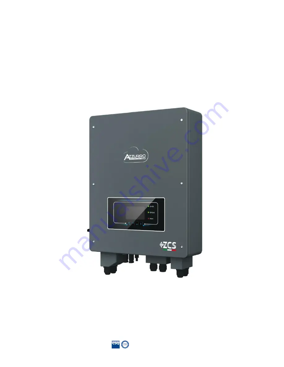
Hybrid Inverter 

1PH HYD3000-HYD6000-ZSS 

User Manual 


Summary of Contents for AZZURRO HYD3000

Page 1: ... 03225010481 REA AR no 94189 ISO 9001 Certified Company Certificate no 9151 CNS0 IT 17778 Zucchetti Centro Sistemi S p A Green Innovation Division Via Lungarno 248 52028 Terranuova Bracciolini Arezzo Italy tel 39 055 91971 fax 39 055 9197515 innovation zcscompany com zcs pec it www zcsazzurro com Hybrid Inverter 1PH HYD3000 HYD6000 ZSS User Manual ...

Page 2: ... 6 Assembly instructions 15 4 Electrical connections 17 4 1 Connecting the battery 18 4 2 Connecting a Pylontech battery 19 4 2 1 Connecting a single battery 19 4 2 2 Connecting multiple batteries in parallel 20 4 3 Connecting a WeCo battery 22 4 3 1 Connecting a single battery 22 4 3 2 Connecting multiple batteries in parallel 22 4 4 Photovoltaic connection 25 4 5 CT Battery Communication RS485 C...

Page 3: ...ioning 53 7 1 Checking the settings 56 8 Technical specifications 58 9 Troubleshooting 59 9 1 Maintenance 65 10 Uninstalling 66 10 1 Uninstallation steps 66 10 2 Packaging 66 10 3 Storage 66 10 4 Disposal 66 11 Monitoring systems 67 11 1 External Wi Fi adapter 67 11 1 1 Installation 67 11 1 2 Configuration 68 11 1 3 Verification 77 11 1 4 Troubleshooting 80 11 2 Ethernet adapter 84 11 2 1 Installa...

Page 4: ...plant Copyright statement Copyright of this manual belongs to Zucchetti Centro Sistemi S p A No part of this manual including the software etc may be copied reproduced or distributed in any form or by any means without the permission of Zucchetti Centro Sistemi S p A All rights reserved ZCS reserves the right to final interpretation This manual is subject to change based on feedback from users ins...

Page 5: ...describes the assembly installation electrical connections commissioning maintenance and troubleshooting of the 1PH HYD3000 HYD6000 ZSS hybrid inverter Keep this manual so that it is accessible at all times Recipients This manual is intended for qualified technical personnel installers technicians electricians technical support personnel or anyone who is qualified and certified to operate a photov...

Page 6: ...mode when the energy produced by the PV field is greater than that required by the utilities the 1PH HYD3000 HYD6000 ZSS inverter charges the battery using the photovoltaic energy in excess and when the photovoltaic energy is lower than that required the inverter uses the energy stored in the battery to supply current to the local load In the event of a power failure or by switching on the inverte...

Page 7: ...ng to the following instructions Place the inverter on suitable load bearing supports with sufficient load capacity such as walls or racks and make sure that the inverter is positioned vertically Choose a suitable location for the installation of the electrical equipment Make sure there is sufficient space for heat dispersion and to accommodate future maintenance Maintain adequate ventilation and ...

Page 8: ...DC power cables from the battery to the inverter must be at least 90A Use short DC power cables to prevent voltage drops and power losses Use a multimeter to check the battery polarity and voltage before turning on the power Make sure that the connections are made according to the instructions in this manual Use the multimeter to check the PV voltage and polarity before closing the PV switch Make ...

Page 9: ...verter and batteries before connecting disconnecting the battery terminals f Both the positive and negative polarities must be isolated from the ground 2 3 Symbols on the inverter Some safety symbols are located on the inverter Read and understand the content of the symbols before installing the inverter This symbol indicates a hazardous situation which if not avoided will result in injury Risk of...

Page 10: ...00 HYD6000 ZSS inverter This indicates the degree of protection of the equipment in accordance with the IEC 70 1 EN 60529 June 1997 standard Positive polarity and negative polarity of the DC voltage Photovoltaic and Battery This side up The 1PH HYD3000 HYD6000 ZSS inverter must always be transported handled and stored in such a way that the arrows are always pointing upwards ...

Page 11: ...ring delivery Carefully check the packaging and product fittings before installation Caution Figure 2 Diagram of a system on which an 1PH HYD3000 HYD6000 ZSS hybrid is installed 1 DC switch 6 Current transformer port 2 Battery input terminals 7 Critical load connection port 3 PV input terminals 8 Grid connection port 4 Wi Fi GPRS adaptor 9 LCD 5 BMS communication interface 10 Vent valve 3 2 Conten...

Page 12: ... cable 2 PV input terminals 2 PV input terminals 1 NTC 3M long Figure 3 Components and accessories inside in the packaging 3 3 Installation environment Choose a dry clean and orderly place suitable for installation Ambient temperature range 25 C 60 C Relative humidity 0 100 non condensing The 1PH HYD3000 HYD6000 ZSS inverter must be installed in a well ventilated area Do not place flammable or exp...

Page 13: ...meter 6 mm Used to make holes in the wall 2 Screwdriver Used for the wiring 3 Cable stripper Used for stripping the wires 4 4mm Allen key Used for tightening the screws to connect the rear panel to the inverter 5 Crimping tools Used for crimping the power cables 6 Multi meter Used for checking the grounding connection 7 Marker Used for marking 8 Tape measure Used for measuring distances 9 Level Us...

Page 14: ...Dust mask Must be worn by operators 3 5 Wall installation position The 1PH HYD3000 HYD6000 ZSS inverter must be mounted vertically to ensure rapid heat dissipation Install the 1PH HYD3000 HYD6000 ZSS inverter in a location protected from direct sunlight and from possible snow accumulation Ensure that the installation position is well ventilated Figure 4 Installation position of the 1PH HYD3000 HYD...

Page 15: ...o shallow nor too deep Step 3 Fix the mounting bracket to the wall using dowels and flat washers Step 4 Place the 1PH HYD3000 HYD6000 ZSS inverter on the mounting bracket Step 5 Use the grounding hole of the heatsink to ground the 1PH HYD3000 HYD6000 ZSS inverter Step 6 OPTIONAL the 1PH HYD3000 HYD6000 ZSS inverter can be fixed to the mounting bracket Note For safety reasons ZCS Spa and or its par...

Page 16: ...ication MD AL GI 00 Rev 1 1 of 16 03 2021 Application GID 16 94 Inverters and or battery packs installed at higher heights must be moved to the ground before they can be repaired or serviced Figure 5 Instructions for installing the storage inverter and battery pack ...

Page 17: ... AC disconnecting device circuit breaker must be installed between the 1PH HYD3000 HYD6000 ZSS inverter and the power grid It is also recommended to use a differential with a trip threshold of 300 mA between the 1PH HYD3000 HYD6000 ZSS inverter and power grid For safety and proper functioning of the system it is important to use a cable of the appropriate type and size for the electrical connectio...

Page 18: ... 1 1 16 03 2021 Identification MD AL GI 00 Rev 1 1 of 16 03 2021 Application GID 18 94 Figure 6 Electrical Connections 4 1 Connecting the battery Figure 7 Connecting the battery measure polarity voltage of the battery cables before connection ...

Page 19: ...ting a Pylontech battery 4 2 1 Connecting a single battery This cable must be connected to the battery by inserting the RJ45 8 pin plug into the appropriate connection 1 In the case of Pylontech batteries insert the plug into the BMS CAN port of the single battery Figure 8 Pylontech communication cable to be inserted into the battery communication input 2 Ensure that the order of the DIP switches ...

Page 20: ...e two power cables e g the positive orange one to the master battery inserting the fast contact into the appropriate terminal then connect the other cable e g the negative black one to the last battery of the pack as shown in the figure below Finally run the batteries in parallel using the short jumpers supplied with the battery or those with a length of 0 6 m or 1 5 m available on request codes Z...

Page 21: ... CONNECTION PORT 1 of the Slave 1 battery insert the free end of this cable into the third battery called Slave 2 This procedure will be repeated for all the elements of the battery pack In the end all the LINK PORTS will be occupied by the communication cable except for the master battery LINK PORT 0 free and the last Slave battery LINK PORT 1 free Figure 11 Connecting the communication cable bet...

Page 22: ... WeCo battery b Make sure that the DIP switches are set as shown in the figure c Connect the ground cable to the battery through the threaded hole NOTE To connect the WECO batteries use the blue or grey communication cable contained in the battery kit Figure 13 Connecting the communication cable to the WeCo battery 4 3 2 Connecting multiple batteries in parallel If multiple batteries are present a...

Page 23: ...teries this will now become the MASTER battery d The MASTER must be connected to the communication cable inside the battery box starting from the RS485 B port and arriving at the RS485 A communication port of the Slave 1 battery Attention do not connect the RS485 A port to the Master battery Figure 14 Communication cable between the batteries e In case of additional batteries the communication cab...

Page 24: ...H HYD3000 HYD6000 ZSS Rev 1 1 16 03 2021 Identification MD AL GI 00 Rev 1 1 of 16 03 2021 Application GID 24 94 Figure 16 Parallel connection of three WeCo batteries Figure 17 Parallel connection of four WeCo batteries ...

Page 25: ...nection Recommended specifications for DC input cables Cross sectional area mm2 AWG Outer diameter of cable mm2 Range Recommended value 4 0 6 0 11 9 4 0 11 4 5 7 8 Procedure Step 1 Prepare the positive and negative photovoltaic cables Figure 19 Preparing the positive and negative photovoltaic cables Step 2 Insert the crimped positive and negative cables into the corresponding photovoltaic connecto...

Page 26: ...less than 600V DC and that the polarities of the photovoltaic cables are correct Insert the positive and negative connectors in the 1PH HYD3000 HYD6000 ZSS inverter until you hear a click sound as show in Fig 9 Figure 21 Connecting the photovoltaic connectors Before removing the positive and negative PV connectors make sure that the DC CIRCUIT BREAKER is OPEN Caution Removal procedure Use a MC4 wr...

Page 27: ... be set to parallel mode Note Depending on the type of inverter select the appropriate inverter accessories cables fuse holders fuses switches etc The open circuit voltage of the photovoltaic system must be lower than the maximum DC input voltage of the inverter The output voltage of the strings must be compatible with the MPPT voltage range The positive and negative polarities of the panel on the...

Page 28: ...Ta Figure 24 CT connections Step 1 Refer to figure 12 for the correct position of the CTa Wrap the CTa around the L wire of the mains power supply Step 2 If necessary network cables and terminal caps can be used to extend the CTa wires the maximum length of the cables is 200m TC Wire Extension network cable HYD3000 HYD6000 Red Orange white orange brown white brown CT Black Green white green blue w...

Page 29: ...in the inverter s packaging For WeCo batteries the cable is found inside the battery packaging Connect one terminal to the battery BAT and the other to the inverter inverter Route the communication cable inverter side through the cable gland on the left side of the cover then insert the connector into the CAN port Insert the battery side connector BAT end into the CAN port of the PYLONTECH or WeCo...

Page 30: ...H pin4 CANL pin5 RS485 port 485A pin1 pin8 485A pin2 pin7 Figure 27 End of Pylontech communication cable with inverter side terminal in the CAN input Step 7 Replace the waterproof cover and secure it with the 4 screws tighten the cable gland Step 8 Below are some simplified diagrams showing the correct and incorrect installation of the current sensors As shown in the figure the CTa current sensor ...

Page 31: ...current sensors The figure below shows an incorrect positioning of the CTa sensor consumption reading Figure 29 Incorrect positioning of the current sensors CTa reading of the utilities only In case of multiple phase cables connected in parallel directly under the import export meter make sure all the phase cables pass through the CTa sensor as shown in the figure ...

Page 32: ...nection Step 1 Loosen the 4 screws part A using a screwdriver fig 15 Step 2 Remove the waterproof cover part B loosen the cable gland part C and then remove the cap part G Step 3 Route a three pole cable through the GRID cable gland then connect the three wires to the corresponding terminal blocks BROWN L BLUE N YELLOW GREEN PE Step 4 Fasten the waterproof cover using the 4 screws Figure 31 Connec...

Page 33: ...ch is in the 0 position When checking repairing the 1PH HYD3000 HYD6000 ZSS inverter make sure that the change over switch is in the 0 position and that the 1PH HYD3000 HYD6000 ZSS inverter is disconnected from the grid Caution Under normal conditions change over switch is in position 1 The 1PH HYD3000 HYD6000 ZSS inverter can supply power to critical loads in the event of a power failure If the 1...

Page 34: ...er the main interface Press Up to enter the upper menu or to increase the value by 1 Press Down to enter the lower menu or to decrease the value by 1 Press OK to select the option of the current menu or to move to the next number 5 2 Indicator lights and operating status Status of the 1PH HYD3000 HYD6000 ZSS inverter On Grid Green light Off Grid Green light Alarm Red light On grid On Standby On Gr...

Page 35: ...s OFF 6 An AC switch is correctly connected between the LOAD port of the 1PH HYD3000 HYD6000 ZSS inverter and the critical load and the switch is OFF 7 The communication cable for lithium batteries has been correctly connected 6 2 First start up of the inverter 1 Make sure that the AC side switch of the inverter is lowered so that no power is supplied to the device 2 Make sure that the rotating di...

Page 36: ...ess the red SW button of the master battery for about one second at this point the LEDs of all the batteries will light up in sequence and after a few seconds will turn off except for the RUN indicating LED After this wait for the display to turn on Figure 36 Battery status after setting the POWER switch to ON and pressing the SW button In the case of WeCo batteries press the RUN button for about ...

Page 37: ... starts working 1 Set the system time 8 Set the minimum discharge voltage 2 Set the country 9 Set the maximum discharge voltage 3 Select the type of battery 10 Set the minimum voltage protection 4 Set the battery capacity 11 Set the depth of discharge 5 Set the maximum charge voltage 12 Set the no load discharge voltage 6 Set the maximum charge current 13 Set the full charge voltage 7 Set the maxi...

Page 38: ...nmark 16 UK G83 27 New Zealand 06 Greece Mainland 17 Greece Islands 28 Brazil 07 Netherlands 18 EU EN50438 29 Slovakia 08 Belgium 19 IEC EN61727 30 Slovakia SSE 09 UK G59 20 Korea 31 Slovakia ZSD 10 China 21 Sweden 32 CEI0 21 In Areti It is essential to make sure that you have selected the correct country code according to the requirements of the local authority For this purpose consult a professi...

Page 39: ...uction Household Consumption If the battery is not charged the 1PH HYD3000 HYD6000 ZSS inverter will charge the battery When Photovoltaic Production Household Consumption If the battery is not discharged the 1PH HYD3000 HYD6000 ZSS inverter will discharge the battery and provide power to the domestic load 6 4 Main menu In the main interface press the Down button to enter the page with the grid bat...

Page 40: ...2 PV1 Current 3 PV1 Power 4 PV2 Voltage 5 PV2 Current 6 PV2 Power 7 Inverter Temp In the main interface press Back to enter the main menu The main menu has the following five options Main interface Press Back Up Down 1 Settings 2 Advanced settings 3 Event list 4 System Info 5 SW Update 6 Prod Statistics 6 4 1 Basic settings 1 Settings Press OK Up Down 1 Language 2 Date and Time 3 Working Mode 4 PV...

Page 41: ...he time the format is Year Month Day Hours Minutes Seconds Press Up or Down to change the first digit press OK to move to the next digit After entering the current time press OK 3 Energy Storage Mode Select 3 Energy Storage Mode and press OK to enter the interface for setting the energy storage mode 3 Energy Storage Mode Up Down 1 Select automatic mode 2 Select charge mode 3 Select Time Zone mode ...

Page 42: ...the 1PH HYD3000 HYD6000 ZSS inverter will not charge or discharge the battery 2 If PV production LOAD consumption the surplus power will be stored in the battery 3 If the battery is fully charged or already at max charge power the surplus energy will be exported to the grid 4 If PV production LOAD consumption then it will discharge the battery to supply power to the load ...

Page 43: ...ate both independently and in parallel If the PV strings are connected in parallel parallel mode must be selected before connecting to the inverter otherwise the default configuration independent mode must be used After changing the PV input mode restart the 1PH HYD3000 HYD6000 ZSS inverter to validate this change 5 EPS Mode The EPS mode allows enabling the EPS output for critical loads 5 Select E...

Page 44: ...7 Self test Up Down 1 Fast self test 2 STD Self test 3 Set QF time 3 Set QV time 5 Control 81 S1 1 Fast self test Select 1 Fast self test then press OK to start the fast self test Start Self Test Press OK to start Testing 59 S1 Wait Test 59 S1 OK Wait Testing 59 S2 Wait Test 59 S2 OK Wait Testing 27 S1 Wait Test 27 S1 OK Wait Testing 27 S2 Wait Test 27 S2 OK Wait Testing 81 S1 Wait Test 81 S1 OK W...

Page 45: ...t 3 PF Time Setting then press OK The following will appear on the screen Set s Press Up or Down to change the first digit press OK to move to the next digit After changing all the digits press OK Testing 81 S2 Wait Test 81 S2 OK Wait Testing 81 S1 Wait Test 81 S1 OK Wait Testing 81 S2 Wait Test 81 S2 OK Press OK OK self test Press Down 59 S1 threshold 253V 900ms Press Down 59 S1 228V 902ms Press ...

Page 46: ...p or Down to Enable 81 S1 or Disable 81 S1 press OK 6 4 2 Advanced settings 2 Advanced settings Enter password 0715 Up Down 1 Battery Parameters 2 Delete Energy Data 3 Clear events 4 Set Country 5 Anti Reflux 6 IV Curve Scan 7 Battery Active 8 DRMs0 Control 9 Set Safety parameters Select 2 Advanced Settings and press OK Enter password appears Enter the password 0715 press Up or Down to change the ...

Page 47: ...arameters do not have to be changed 2 Reset Energy Data Select 2 Reset Energy then press OK to reset the energy data 3 Clear events Select 3 Clear Events then press OK to clear all the events 4 Country refer to Set Country Select 4 Country press OK the settings of the current country appear Press Up or Down to change the first digit press OK to move to the next digit Enter the new country code and...

Page 48: ...can period or force an immediate scan 7 Safety parameters and other functions not previously described that appear in the user interface Contact ZCS Technical Support for more information 6 4 3 Event list 3 Event list Up Down 1 List of current events 2 List of Historical events 1PH HYD3000 HYD6000 ZSS inverter event list including the lists of current and historical events 1 List of current events...

Page 49: ...ersion Hardware version Energy Level Inverter Information 2 Country Photovoltaic Input Mode Energy Storage Mode Inverter Information 3 RS485 address EPS Mode IV Curve Scan Anti Reflux Inverter Information 4 DRMs0 Control PF Time Setting QV Time Setting Power factor 2 Battery Info Battery Info 0 Battery type Battery capacity Depth of discharge Maximum charge A Battery Info 1 Over V Protection Maxim...

Page 50: ...ergy statistics 3 Safety Parameters Safety parameters 0 OVP 1 OVP 2 UVP 1 UVP 2 Safety parameters 1 OFP 1 OFP 2 UFP 1 UFP 2 Safety parameters 2 OVP 10mins 5 Energy Statistics 1 Daily Weekly Photovoltaic KWH Charge KWH Export KWH Import KWH Charge KWH Discharge KWH 2 Year Duration Photovoltaic KWH Charge KWH Export KWH Import KWH Charge ...

Page 51: ...t press OK to move to the next digit when 0715 appears on the screen press OK The 1PH HYD3000 HYD6000 ZSS inverter will automatically start the software update Detailed Procedure for Firmware Update Step 1 Turn off the AC switch grid and load then turn off the batteries and the photovoltaic switch Remove the waterproof communication cover If the communication cables CAN RS485 NTC CT have been conn...

Page 52: ...e update Step 7 When the firmware update is complete turn off the AC mains switch close the waterproof communication cover with the four screws then turn on the AC mains switch again Turn on the battery switch turn on the photovoltaic switch the 1PH HYD3000 HYD6000 ZSS inverter will automatically resume operation NOTE If DSP Communication error DSP1 update error or DSP2 update error appear on the ...

Page 53: ...he inverter follow these steps 1 Switch off any source of photovoltaic generation by turning the circuit breaker to the OFF position 2 Lower the protection switch of the 1PH HYD3000 HYD6000 ZSS inverter The inverter will remain switched on but will go into error due to a lack of AC power if the EPS function is enabled it will feed the priority loads 3 Power up the inverter by pulling up the AC swi...

Page 54: ...there are no other power flows from either the photovoltaic system or the battery 5 Once the countdown is over the batteries will start to deliver power according to the availability towards the utility trying to reset the consumption from the grid During this period check that the a value of the consumption remains constant as the power supplied by the battery increases during discharge b The pow...

Page 55: ...emains constant as the photovoltaic power increases b Depending on the photovoltaic production the system will operate according to its working mode c The value of PV production shown on the display is in line with the real photovoltaic production visible on the photovoltaic inverter 8 If the above are not verified check the positioning of the CTs and the direction by consulting the correct instal...

Page 56: ... fourth key 1 4 To scroll through the images press the third key Country Check that the country code is correct for the regulation in force PV Input Mode Check that the correct setting has been set according to the system configuration Working mode in order to minimise exchanges with the grid the correct mode will be Automatic Mode RS485 Address check that it has a value of 01 so that you can moni...

Page 57: ...e insulation resistance is higher than the limits imposed by the standard Battery type check if the battery model on the display is consistent with the batteries installed Battery capacity the system will show the total capacity of the batteries 1 Pylontech 50 Ah 2 Pylontech 100Ah n Pylontech n x 50Ah 1 WeCo 86 Ah 2 WeCo 172Ah n WeCo n x 86Ah Depth of discharge check the depth of discharge values ...

Page 58: ...anual 1PH HYD3000 HYD6000 ZSS Rev 1 1 16 03 2021 Identification MD AL GI 00 Rev 1 1 of 16 03 2021 Application GID 58 94 8 Technical specifications TECHNICAL DATA HYD3000 HYD3600 HYD4000 HYD4600 HYD5000 HYD6000 ...

Page 59: ...e 1PH HYD3000 HYD6000 ZSS inverter If the grid voltage frequency is NOT within the acceptable range and the AC wiring is correct but the alarm occurs repeatedly contact ZCS Technical Support to change the grid overvoltage undervoltage overfrequency and underfrequency protection points after obtaining approval from the local grid operator ID02 GridUVP The grid voltage is too low ID03 GridOFP The gr...

Page 60: ... is too high and has triggered the hardware protection ID12 HwBatOCP The battery current is too high and has triggered the hardware protection ID13 GFCI OCP The GFCI sampling value between the master DSP and slave DSP is not suitable If the fault occurs occasionally the likely cause is that the external circuits are occasionally in an abnormal state Once the fault has been eliminated the inverter ...

Page 61: ...s too high If the fault occurs frequently contact ZCS Technical Support ID28 DciOCP The DCI is too high ID28 ID31 are internal faults of the 1PH HYD3000 HYD6000 ZSS inverter switch it off wait 5 minutes and then switch it back on again Check if the problem has been resolved If not contact ZCS Technical Support ID29 SwOCPInstant The grid current is too high ID30 BuckOCP The buck current is too high...

Page 62: ...n cable between battery HYD ES inverter It s recommended to use CAN communication For PYLONTECH US2000 PLUS battery and you re using RS485 communication the ADD DIP switch should be all down ID53 SpiCommLose SPI communication is fault ID53 ID55 are internal faults of HYD3000 HYD6000 ZSS inverter switch OFF HYD3000 HYD6000 ZSS inverter wait for 5 minutes then switch ON HYD3000 HYD6000 ZSS inverter ...

Page 63: ...switch it back on again Check if the problem has been resolved If not contact ZCS Technical Support ID73 UnrecoverIPVInstant The input current is too high and has caused an unrecoverable fault ID74 UnrecoverPvConfigSetWro ng Incorrect input mode Check the settings of the photovoltaic input mode parallel independent mode of the 1PH HYD3000 HYD6000 ZSS inverter If this is not correct change the phot...

Page 64: ... Check whether the photovoltaic and grid conditions meet the charging conditions ID94 Software version is not consistent The firmware version installed is not suitable for the type of inverter Contact Technical Support to update the software ID95 CommEEPROMFault The EEPROM communication board is faulty ID95 ID96 are internal faults of the 1PH HYD3000 HYD6000 ZSS inverter switch it off wait 5 minut...

Page 65: ...ection while discharging 9 1 Maintenance Inverters generally do not require daily or routine maintenance In any case for proper long term operation of the inverter make sure that the heatsink for cooling the inverter has enough space to ensure adequate ventilation and that it is not obstructed by dust or other items Cleaning the inverter Use an air compressor a soft dry cloth or a soft bristled br...

Page 66: ...rature is between 25 and 60 C 10 4 Disposal Zucchetti Centro Sistemi S p a is not liable for the disposal of the equipment or parts thereof that does not take place according to the regulations and standards in force in the country of installation The symbol of the crossed out wheeled bin indicates that the equipment at the end of its useful life must be disposed of separately from household waste...

Page 67: ...to monitor the inverter the RS485 communication address must be set to 01 directly from the display Installation tools Cross screwdriver External Wi Fi adapter 1 Switch off the inverter following the procedure described in this manual 2 Remove the cover for accessing the Wi Fi connector on the bottom of the inverter by unscrewing the two cross head screws a or by unscrewing the cover b as shown in...

Page 68: ...o the Wi Fi modem Tools required for configuration Smartphone PC or tablet Go to front of the inverter and search for the Wi Fi network using a smartphone PC or tablet making sure that the signal from the home Wi Fi network reaches the place where the inverter is installed If the Wi Fi signal is present at the location where the inverter is installed the configuration procedure can begin If the Wi...

Page 69: ...eft and Android smartphone right Note Disconnect from any Wi Fi networks to which you are connected by removing automatic access Figure 43 Disabling automatic reconnection to a network 2 Connect to a Wi Fi network generated by the inverter s Wi Fi adapter i e AP_ where indicates the serial number of the Wi Fi adapter shown on the label of the device which operates as an access point ...

Page 70: ...Android smartphone right 3 If you are using a second generation Wi Fi adapter you will be prompted for a password to connect to the inverter s Wi Fi network Use the password found on the box or on the Wi Fi adapter Figure 45 Password of external Wi Fi adapter Note To ensure that the adapter is connected to the PC or smartphone during the configuration procedure enable automatic reconnection of the...

Page 71: ... is not able to provide internet access confirm to maintain the Wi Fi connection even if the internet is not available Figure 47 Screen indicating that the Internet cannot be accessed 4 Open a browser Google Chrome Safari Firefox and enter the IP address 10 10 100 254 in the address bar at the top of the screen In the box that appears enter admin as both the Username and Password ...

Page 72: ...en for accessing the web server to configure the Wi Fi adapter 5 The status screen will open showing the logger information such as the serial number and firmware version Check that the Inverter Information fields are filled in with the inverter information The language of the page can be changed using the command in the top right hand corner ...

Page 73: ... left hand column 7 In the new screen that opens select the Wi Fi network to which you want to connect the Wi Fi adapter making sure that the Received Signal Strength Indicator RSSI is greater than 30 If the network is not visible press the Refresh button Note check that the signal strength is greater than 30 if not bring the router closer or install a repeater or signal amplifier Click Next ...

Page 74: ... Fi network Wi Fi modem clicking on Show Password to make sure it is correct the password should not contain special characters and spaces Note During this step the system is not able to ensure that the password entered is the one actually requested by the modem therefore please make sure you enter the correct password Also check that the box below is set to Enable Then click Next and wait a few s...

Page 75: ...ation MD AL GI 00 Rev 1 1 of 16 03 2021 Application GID 75 94 Figure 51 Screen for entering the password of the wireless network 2 9 Click Next again without ticking any of the options relating to the system security Figure 52 Screen for setting the security options 3 ...

Page 76: ...l configuration screen 4 11 At this point if the configuration of the adapter is successful the last configuration screen will appear and the telephone or PC will unpair from the inverter s Wi Fi network 12 Manually close the web page with the Close key on the PC por remove it from the background of the telephone Figure 54 Successful configuration screen ...

Page 77: ...ence of the Wi Fi network in the list will confirm the successful configuration of the Wi Fi adapter Figure 55 Wi Fi network search on Smartphone iOS and Android Access point of the Wi Fi adapter is no longer visible If the Wi Fi network is still present in the list connect to it again and enter the status page Check the following information a Wireless STA mode i Router SSID Router name ii Signal...

Page 78: ... 2021 Application GID 78 94 Figure 56 Status screen Status of LEDs present on the adapter 1 Initial status NET left LED off COM central LED steady on READY right LED flashing on Figure 57 Initial status of LEDs 2 Final status NET left LED steady on COM central LED steady on READY right LED flashing on ...

Page 79: ...not successful i e the wrong router password was entered or the device was disconnected during connection It is necessary to reset the adapter Press the Reset button for 10 seconds and release After a few seconds the LEDs will turn off and READY will start to flash quickly The adapter has now returned to its initial state At this point the configuration procedure can be repeated again The adapter ...

Page 80: ...he left go to System Info and press ENTER to enter the submenu Scroll down to the Modbus address parameter and make sure it is set to 01 and in any case other than 00 If the value is not 01 go to Settings basic settings for hybrid inverters and enter the Modbus Address menu where the 01 value can be set Check that the Wi Fi adapter is correctly and securely connected to the inverter making sure to...

Page 81: ...ing configuration If necessary increase it by using a network extender or a router dedicated to inverter monitoring Check that the router has access to the network and that the connection is stable check that a PC or smartphone can access the Internet Check that port 80 of the router is open and enabled to send data Reset the adapter as described in the previous section If at the end of the previo...

Page 82: ...nable the Wi Fi mobile hotspot option wait a few seconds for the wireless network to be created To change the name of the wireless network SSID or your password select Configure Wi Fi hotspot Figure 63 Configuration of an Android smartphone as a hotspot router Using an iPhone as a modem a In order to share the iPhone connection verify that the 3G LTE network is active by going to Settings Mobile P...

Page 83: ... choose the one activated by the smartphone and then enter the password associated with it which can be changed from the personal hotspot settings If at the end of configuration Connected appears next to Remote Server A then the problem is with the home router It is therefore advisable to check the brand and model of the home router you are trying to connect to the Wi Fi adapter some router brands...

Page 84: ...rk and in operation in order to achieve stable data transmission from the inverter to the server In order to monitor the inverter the RS485 communication address must be set to 01 directly from the display Installation tools Cross screwdriver Ethernet adapter Shielded network Cat 5 or Cat 6 crimped with RJ45 connectors 1 Switch off the inverter following the procedure described in this manual 2 Re...

Page 85: ...ugh then insert the network cable network into the appropriate port on the inside of the adapter and tighten the ring nut and cable gland to ensure a stable connection Figure 66 Inserting the network cable inside the device 4 Connect the Ethernet adapter to the appropriate port making sure to follow the direction of the connection and ensure correct contact between the two parts a b Figure 67 Inse...

Page 86: ...network cable to the modem 6 Switch on the inverter by following the procedure described in the manual 7 Unlike Wi Fi cards the Ethernet adapter does not need to be configured and starts transmitting data shortly after the inverter is switched on 11 2 2 Verification Wait two minutes after installing the adapter and check the status of the LEDs on the device Status of LEDs present on the adapter 1 ...

Page 87: ...94 Figure 69 Initial status of LEDs 2 Final status NET left LED steady on COM central LED steady on SER right LED flashing on Figure 70 Final status of LEDs 11 2 3 Troubleshooting Status of LEDs present on the adapter 1 Irregular communication with inverter NET left LED steady on COM central LED off SER right LED flashing on ...

Page 88: ...t to 01 and in any case other than 00 If the value is not 01 go to Settings basic settings for hybrid inverters and enter the Modbus Address menu where the 01 value can be set Check that the Ethernet adapter is correctly and securely connected to the inverter making sure to tighten the two cross head screws provided Check that the network cable is correctly inserted into the device and modem and t...

Page 89: ...The ZCS 4G adapters are sold with a virtual SIM integrated into the device with data traffic fee included for10 years which is adequate for the proper transmission of data to monitor the inverter In order to monitor the inverter the RS485 communication address must be set to 01 directly from the display 11 3 1 Installation Installation must be carried out for all inverters compatible with the adap...

Page 90: ...ID 90 94 a b Figure 73 Port of the 4G adapter 6 Insert the 4G adapter into the appropriate port making sure to follow the direction of the connection and ensure correct contact between the two parts Secure the 4G adapter by tightening the two screws inside the package a b Figure 74 Inserting and securing the 4G adapter ...

Page 91: ...ext 3 minutes check the status of the LEDs on the device to ensure that the device is configured correctly Status of LEDs present on the adapter 1 Initial status NET left LED off COM central LED flashing on SER right LED flashing on Figure 75 Initial status of LEDs 2 Registration NET left LED flashes rapidly for about 50 seconds the registration process takes about 30 seconds COM central LED flash...

Page 92: ... and adapter Check the Modbus address set on the inverter Enter the main menu with the ESC key first key on the left go to System Info and press ENTER to enter the submenu Scroll down to the Modbus address parameter and make sure it is set to 01 and in any case other than 00 If the value is not 01 go to Settings basic settings for hybrid inverters and enter the Modbus Address menu where the 01 val...

Page 93: ...nd remote server Check that the 4G signal is present in the installation location the adapter uses the Vodafone network for 4G transmission if this network is not present or the signal is weak the SIM will use a different network or will limit the data transmission speed Ensure that the installation location is suitable for 4G signal transmission and that there are no obstacles that could affect d...

Page 94: ...entification MD AL GI 00 Rev 1 1 of 16 03 2021 Application GID 94 94 12 Warranty terms and conditions To view the Warranty Terms and Conditions offered by ZCS Azzurro please refer to the documentation inside the product box and on the website www zcsazzurro com ...

Reviews: