background image

9 / 96

CAYMAN

Version 01 - Revision 00

09/05/2017

GENEral INforMatIoN

2.1 

lIst of supplIEd doCuMENtatIoN

The following documents are provided together with this Manual:


∂ EC declaration of incorporation;


∂ hydraulic motor manual;


∂ hydraulic diagram;


∂ spare parts catalogue�

After the attachment is installed at the customer’s premises, the following documents are provided in hard 
copy:


∂ notification of document delivery, once this Manual and the documents accompanying the Manual itself 

are handed over;


∂ test report, if test results are positive,

and they are to be considered an essential part of the documents accompanying the Manual�

2.2 

INtEllECtual propErty rIGhts

All the information, drawings, diagrams and whatever else is contained in this Manual and the accompanying 
documentation are confidential�
No part of such information can be reproduced or communicated to third parties without prior authorisation 
from the Manufacturer, who is its exclusive owner�
The only person authorised to use these documents is the Customer to whom the Manual is supplied as an 
essential part of the attachment, for the sole purpose of properly carrying out all the operations relative to the 
various life cycle phases of the attachment itself�

2.3 

purposE of thE MaNual

This Manual is an essential part of the attachment and is intended for anyone operating the latter or interacting 
with its users�
This Manual aims to provide all the necessary information to:


∂ quickly identify all the parts making up the attachment;


∂ define the tasks, duties and operating limits of the various users;


∂ execute all the intended operations correctly prior to using, servicing, and scrapping the attachment;


∂ guarantee the health and safety of the personnel who operate on the attachment in various capacities;


∂ make sure that the attachment works efficiently�

The Manufacturer is considered relieved from all civil or criminal liability resulting from failure to comply with 
the instructions contained in this Manual�

Summary of Contents for CAYMAN FCE II Series

Page 1: ...EN www zatoshredder com rECyClING dEMolItIoN SAFETY OPERATION AND MAINTENANCE MANUAL cayman DEMOLITION SHEAR FCE II SERIES...

Page 2: ......

Page 3: ...forfeiture conditions 18 3 General safety regulations 20 3 1 General regulations Personnel training 20 3 2 General regulations Safety of workplaces 20 3 3 General regulations Work area 21 3 4 General...

Page 4: ...e 56 6 2 Using the attachment 56 6 2 1 Preliminary checks 57 6 2 2 Work cycle 57 6 2 3 End of work shift 58 7 Maintenance instructions 59 7 1 Safety measures to be implemented for maintenance 59 7 1 1...

Page 5: ...CAYMAN Version 01 Revision 00 09 05 2017 7 3 Summarised table of maintenance frequency 86 7 4 Troubleshooting 88 8 Instructions for demolition and disposal 91 9 Index of figures 92 10 Index of tables...

Page 6: ...6 96 CAYMAN Version 01 Revision 00 09 05 2017...

Page 7: ...alle BS Italy Tel 39 030 6461800 Fax 39 030 6801897 Web www zato it E mail info zato it VAT Tax Code 02539520987 1 2 Attachment identification data The identification plate Fig 1 on page 7 of the atta...

Page 8: ...entally damaged detached or should the manufacturer s seal simply come off the customer must inform the manufacturer The components that make up the attachment are built in compliance with the acciden...

Page 9: ...thout prior authorisation from the Manufacturer who is its exclusive owner The only person authorised to use these documents is the Customer to whom the Manual is supplied as an essential part of the...

Page 10: ...apters are numbered progressively starting from 1 The numbering of sub chapters is structured as follows chapter number sub chapter number example 1 1 or 2 10 The numbering of the paragraphs is struct...

Page 11: ...ill be indicated whenever a particular operation described in this Manual requires its use It is mandatory to wear protective gloves when performing the relevant operations It is mandatory to wear pro...

Page 12: ...se the health and safety of people Protection systems include fixed guards mobile guards active or passive safety devices PROTECTION SYSTEMS FIXED GUARDS CASING Components of the attachment used speci...

Page 13: ...hment cyclical functions using the specific control panels 2 5 3 1 Specific definitions and glossary STOP An operation done voluntarily by the Operator to interrupt a process that is underway ATTACHME...

Page 14: ...file and housings for cylindrical screws LINKAGE CONNECTION Flange equipped with perforated plates that connect the excavator arm to the attachment SHIM Steel plate to position between the housing and...

Page 15: ...h Hour Tab 2 Unit of measure 2 6 Updating the Manual Following changes in the attachment construction should the Manual require updating the Manufacturer will strive to provide the Customer with arev...

Page 16: ...hich require in depth knowledge of the attachment and how it operates 2 8 General warnings 2 8 1 Customer s responsibilities Unless specific contractual conditions are implemented the Customer must ad...

Page 17: ...chnical Assistance on page 17 The Manufacturer will not be held liable for any damage caused to people property or any other accidents as a result of any spare parts not being supplied by the Manufact...

Page 18: ...iring or replacing the merchandise under the Manufacturer s unquestionable discretion The Customer has no right to reimbursement for damages and or an extension of the established warranty duration an...

Page 19: ...lacements repairs not described in the Manual or tampering by the Customer or third parties if the safety devices are tampered with or removed except when specifically specified if accessories not sup...

Page 20: ...t contents of the Manual capability of understanding the symbols pictograms drawings diagrams and video messages knowledge of the main hygienic and accident prevention regulations knowledge of the beh...

Page 21: ...tion of the health conditions of Operators related to the duration of the work shift such as fatigue distraction etc ensure Operator training is repeated regularly according to the evolution of risks...

Page 22: ...moving part Do not carry out repairs adjustments cleaning lubrication or maintenance on any pressurised part Donotkeepflammablematerialsuchaspetrol solvents gascylinders etc neartheattachment 3 6 Emer...

Page 23: ...her absorbent granular substances collect it and take it to an appropriate waste disposal site In case of contact with the eyes flush thoroughly with water for 15 minutes If the irritation persists se...

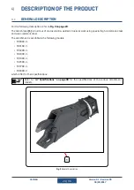
Page 24: ...turdy electro welded structural work using special high resistance steel and wear resistant steel The attachment is available in the following models FCE06R II FCE10R II FCE20R II FCE30R II FCE40R II...

Page 25: ...YMAN Version 01 Revision 00 09 05 2017 4 2 Main components For the following description refer to Fig 3 on page 25 The main components of the attachment are rotating head 1 shears 2 2 1 Fig 3 Main com...

Page 26: ...The rotating head includes hydraulic motor 1 slewing ring 2 swivel hydraulic coupling 3 speed valve 4 hydraulic connection system consisting alternately of flow regulator manifold blocks 5 on both si...

Page 27: ...e steel structure 1 upper jaw 2 jaw 3 no 2 clutches 4 on both sides of the attachment central pin 5 with end flange 5A no 4 main blades 6 with blade shims 6A no 2 guide blades 7 with blade shims 7A an...

Page 28: ...position linkage connection 1 with bolts to mechanically connect the attachment to the machine bucket position arm position linkage connection 2 with bolts to mechanically connect the attachment to th...

Page 29: ...ous material Tab 3 Intended uses 4 5 1 Number of workers 1Only Operator is required to use the attachment Depending on the type of work to be done a second Operator on the ground may be necessary This...

Page 30: ...n terms of the possible movements generated on the part or structure 4 7 Specifications 4 7 1 Hydraulic features Using the attachment with oil flows exceeding the indicated intervals can damage the at...

Page 31: ...e shown in the table below Model A B C FCE06R II 1 620 mm 420 mm 660 mm FCE10R II 1 920 mm 570 mm 835 mm FCE20R II 2 610 mm 710 mm 1 027 mm FCE30R II 2 960 mm 760 mm 1 165 mm FCE40R II 3 390 mm 830 mm...

Page 32: ...the attachment to be installed and the installation position are shown in the table below The minimum machine weights refer to operating conditions on a horizontal surface on a solid surface Model Mac...

Page 33: ...according to the schedule If the noise level exceeds 80 dB A protective earmuffs are mandatory 4 9 Other emission During operation the machine may generate vibrations that can be transmitted to the at...

Page 34: ...cretion 4 14 Description of residual risks Pursuant to EU Directive 2006 42 EC the danger zones are listed below together with the residual risks which cannot be eliminated without compromising the fu...

Page 35: ...tact with hot surfaces Specific requirements Wait for the attachment to cool down before servicing it Danger zone 3 Exposed person Mechanical Technician Stage maintenance Nature of the risk contact wi...

Page 36: ...ion 00 09 05 2017 4 15 Protection systems For the following description refer to Fig 9 on page 36 The machine is equipped with the following protection systems fixed guards 1 protecting the moving par...

Page 37: ...the safety signs applied to the attachment illegible Refer to Fig 10 on page 38 unless otherwise specified The information and warnings applied on the attachment are shown in the table below Pictogram...

Page 38: ...38 96 CAYMAN Version 01 Revision 00 09 05 2017 7 1 2 4 8 5 3 6 Fig 10 Information and warnings applied...

Page 39: ...ility of n 2 Personnel in charge of Handling who have been properly instructed regarding the use of lifting and handling equipment and have the related license During initial installation handling and...

Page 40: ...chment Fig 11 on page 40 can be handled by using a forklift 1 if positioned on a pallet by using a crane or machinery with a similar function 2 In other cases by using the specific lifting points 2A T...

Page 41: ...sition the attachment The equipment used ropes chains forklift truck etc must comply with the regulations in force in the country where the attachment is installed and used and approved for lifting an...

Page 42: ...in the Country where the attachment is installed and used Packaging methods depend on the transport method agreed upon when the order was placed Refer to that agreed on when placing the order The unp...

Page 43: ...ion operations include mechanically connecting the attachment to the machine hydraulically connecting the attachment to the machine Refer to the machine manual for the operations on the machine indica...

Page 44: ...bucket arm from the machine referring to the machine s manual 4 connect the linkage connection 2 to the attachment by using the specific bolts 5 retract the machine cylinder shaft 3 arm position comp...

Page 45: ...45 96 CAYMAN Version 01 Revision 00 09 05 2017 6 3 5 2 1 4 Fig 13 Mechanically connecting the attachment to the machine arm position...

Page 46: ...erring to the machine s manual 3 connect the linkage connection 2 to the attachment by using the specific bolts 4 retract the machine cylinder shaft 3 bucket position completely 5 align the machine ar...

Page 47: ...47 96 CAYMAN Version 01 Revision 00 09 05 2017 6 3 5 2 1 4 Fig 14 Mechanically connecting the attachment to the machine bucket position...

Page 48: ...is on when the machine is switched off the hydraulic flow towards the attachment must stop the machine hydraulic system must not have pressure accumulator tanks so as to prevent the attachment from m...

Page 49: ...referring to the following table Reference Tube function Connection 1 Machine pump discharge SAE 6000 3 4 FLANGE 2 Machine rotation discharge 3 8 G BSP 3 Machine rotation delivery 3 8 G BSP 4 Machine...

Page 50: ...E 3 4 SAE 6000 1 1 2 2 Machine rotation discharge FCE30R II FCE40R II 1 G BSP FCE50R II FCE70R II FCE90R II 3 Machine rotation delivery FCE30R II FCE40R II 1 G BSP FCE50R II FCE70R II FCE90R II 4 Mach...

Page 51: ...pump discharge 3 4 G BSP 2 Machine rotation discharge 1 2 G BSP 3 Machine rotation delivery 1 2 G BSP 4 Machine pump delivery 3 4 G BSP Tab 12 Hydraulic connection by means of quick release hydraulic...

Page 52: ...s are clean and clear of debris 3 make sure the screws and bolts of the shears are tightened correctly by referring to 7 2 2 11 How to make sure the blade screws and bolts are tightened properly on pa...

Page 53: ...erations described below regarding downtime are the responsibility of 2 Operators unless otherwise specified A second operator on the ground is mandatory during downtime operations Do not remove and i...

Page 54: ...let the hydraulic system cool down to ambient temperature 4 loosen the hydraulic couplings with caution 5 disconnect the machine hydraulic tubes from the hydraulic manifolds of the attachment 6 close...

Page 55: ...nstructions 5 7 2 Storage during downtime Refer to 4 13 Environmental conditions required for storage on page 34 for storage during downtime 5 7 3 Restarting after downtime There are no specific resta...

Page 56: ...attachment operation Do not use the attachment above the driver s cab Do not use the attachment to transport demolition scraps Do not shear cut material when the machine is moving Do not leave object...

Page 57: ...shortest possible sling and lift the load only for as long as strictly necessary During the work cycle it is important to carefully evaluate the machine overall stability refer to 4 7 4Machine featur...

Page 58: ...y reducing its capacity at the attachment linking point Fig 21 Orthogonal overturning moment 6 2 3 End of work shift At the end of the work shift carry out the following operations 1 position the atta...

Page 59: ...m Hydraulic oil is toxic and can seriously harm people if it comes into contact with skin and or eyes Failure eveninpart tofollowtheinstructionsinthismanualanditsaccompanyingdocuments for maintenance...

Page 60: ...prevent components from being worn corrective maintenance which includes all operations to be performed so as to restore correct attachment operation following a component malfunction or breakage wear...

Page 61: ...ng ring bolts refer to 7 2 2 9 Slewing ring bolts replacement on page 69 speed valve checks refer to 7 2 2 10 Speed valve checks on page 69 7 2 2 1 General attachment checks The general attachment che...

Page 62: ...hydraulic cylinder head closing screws are intact 2 make sure the hydraulic cylinder head closing screws are tightened properly refer to 7 2 2 11 How to make sure the blade screws and bolts are tight...

Page 63: ...er 1 open close the upper jaw until the spring pad 1 is approximately halfway of the upper jaw rubbing surface 2 remove the fastening screws of the flange 2 3 remove the flange 4 remove any grease fro...

Page 64: ...e intact 2 if there are damaged screws and or bolts replace them 3 make sure the screws and bolts are tightened properly refer to 7 2 2 11 How to make sure the blade screws and bolts are tightened pro...

Page 65: ...upper jaw to reach the position indicated in Fig 23 on page 65 2 measure the distance between the main upper jaw blades 1 and the main jaw blades 2 using a thickness gauge as indicated in Fig 23 on p...

Page 66: ...order 1 open close the upper jaw to reach the position indicated in Fig 24 on page 66 2 measure the distance between the end of the upper jaws 1 and the razor blade 2 using a thickness gauge as indica...

Page 67: ...e upper jaw to make sure the distance stays constant 4 if the distance exceeds 0 2 mm in at least one point adjust the guide blades by referring to 7 2 3 9 Adjusting the guide blades on page 83 5 if t...

Page 68: ...s GRASSO GREASE or because they are coloured red Refer to Fig 26 on page 68 The table below contains information regarding the greasing points frequency and number of pumps Reference Greasing point Fr...

Page 69: ...Slewing ring bolts replacement Before replacing the bolts thoroughly clean the through holes the screws and their nuts in order to remove dirt grease and oil that would compromise their seal The slewi...

Page 70: ...old of the bolts themselves As such all bolts can only be tightened twice after which they need to be replaced Proper screw and bolt tightening is fundamental for the connection to work safely An over...

Page 71: ...the main blades refer to 7 2 3 2 Rotating the main blades on page 73 replacing the main blades refer to 7 2 3 3 Replacing the main blades on page 74 adjusting the main jaw blades refer to 7 2 3 4 Adju...

Page 72: ...l the spring pad 1 is approximately halfway of the upper jaw rubbing surface 2 remove the fastening screws of the flange 2 3 remove the flange 4 Turn the spindle 3 clockwise to push the spring pad aga...

Page 73: ...with 4 cutting profiles Fig 28 on page 73 R0 R1 R2 R3 R0 R2 R1 R3 Fig 28 Main blade cutting profiles The main blades can be rotated three times and require the first time Fig 29 on page 73 rotating e...

Page 74: ...n blades 2 remove the main blades 3 rotate invert them as described above 4 secure the main blades by referring to 7 2 2 11 How to make sure the blade screws and bolts are tightened properly on page 7...

Page 75: ...by referring to 7 2 1 Cleaning on page 60 8 put in the new main blades in reverse order 9 secure the main blades by referring to 7 2 2 11 How to make sure the blade screws and bolts are tightened pro...

Page 76: ...lade 1 perform the operations below in the following order 1 remove the fastening screws on the main blade 2 remove the main blade 3 put remove the shim s 2 into from the main blade housing 4 put in t...

Page 77: ...n its housing by 90 Subsequent rotations must be done in the same direction as the previous one Every 2 blade rotations replace the blade fastening screws to ensure the threading holds For the followi...

Page 78: ...blade referring to 7 2 2 11 How to make sure the blade screws and bolts are tightened properly on page 70 9 put in the guide blades 10 insert the centring plugs on the guide blades 11 secure the guid...

Page 79: ...ve the fastening screws on the razor blade 2 5 remove the razor blade 6 clean the razor blade housing by referring to 7 2 1 Cleaning on page 60 7 put in the new razor blade 8 secure the razor blade by...

Page 80: ...ach guide blade is equipped with 4 cutting profiles Fig 36 on page 80 R0 R1 R2 R3 R0 R1 R2 R3 Fig 36 Guide blade cutting profiles The guide blades can be rotated 3 times and require the first time Fig...

Page 81: ...ts housing by 180 going from cutting profile R2 to R3 To rotate the guide blades perform the operations below in the following order 1 remove the fastening screws on the guide blades 2 insert the dowe...

Page 82: ...e holes of the guide blades 3 pinch the dowel pin to remove the centring pins and guide blades 4 remove the guide blades 5 clean the housing of the guide blades referring to 7 2 1 Cleaning on page 60...

Page 83: ...1 remove the fastening screws on the guide blade 2 insert the dowel pin in the blade face hole of the guide blades 3 pinch the dowel pin to remove the centring pin 4 put remove the shim s 2 into from...

Page 84: ...upper jaw fastening screws 6 tighten the fastening screws with a torque value equal to 1 3 the final value refer to 7 2 2 11 How to make sure the blade screws and bolts are tightened properly on page...

Page 85: ...be performed by a Technician employed or authorised by the Manufacturer and includes all maintenance interventions on the attachment not dealt with in this Manual Inparticular contacttheManufactureri...

Page 86: ...hears Making sure the bla de screws and bolts are tightened properly Daily 7 2 2 5 Checks on the shears on page 64 Shears Checking the blade and upper jaw cutting profile radius Daily 7 2 2 5 Checks o...

Page 87: ...ation of the state of wear of the spring pad Weekly 7 2 2 4 Clutch checks on page 62 Shears Making sure the cen tral pin and end flan ge screws and bolts are tightened properly Weekly 7 2 2 5 Checks o...

Page 88: ...generated it the solution required to resolve it the qualification required to implement the solution Problem Cause Solution Qualification required No power to the upper jaw The machine is not sen din...

Page 89: ...2 3 6 Repla cing the razor blade on page 79 Mechanical Technician The upper jaw speed is less than the parameters originally set or is moving in jerks The speed valve is not working properly Replace t...

Page 90: ...ulic tubes are not connected or they are connected incorrectly Check and properly con nect the hydraulic tu bes to the rotating head by referring to 5 4 2 Hydraulically connec ting the attachment to t...

Page 91: ...clean the attachment as described in 7 2 1 Cleaning on page 60 When the attachment is to be scrapped authorised personnel must separate the materials by type and send the individual parts to waste co...

Page 92: ...8 First start up 53 Fig 19 Downtime instructions 55 Fig 20 Longitudinal overturning moment 57 Fig 21 Orthogonal overturning moment 58 Fig 22 Checking the state of wear of the clutch spring pad 63 Fig...

Page 93: ...tion and warnings applied 37 Tab 9 Rope pull percentage reduction depending on the sling angle 42 Tab 10 Hydraulic connection by means of flow regulation blocks without drainage 49 Tab 11 Hydraulic co...

Page 94: ...94 96 CAYMAN Version 01 Revision 00 09 05 2017...

Page 95: ......

Page 96: ...Via Campi Grandi 23 25080 Prevalle BS Italy Tel 39 030 6461800 Fax 39 030 6801897 e mail info zato it Zato srl Follow Us www zatoshredder com...

Reviews: