background image

Page 26

4.8 DESCRIPTION OF POWER CONNECTIONS

4.8.1 "Dualac2"

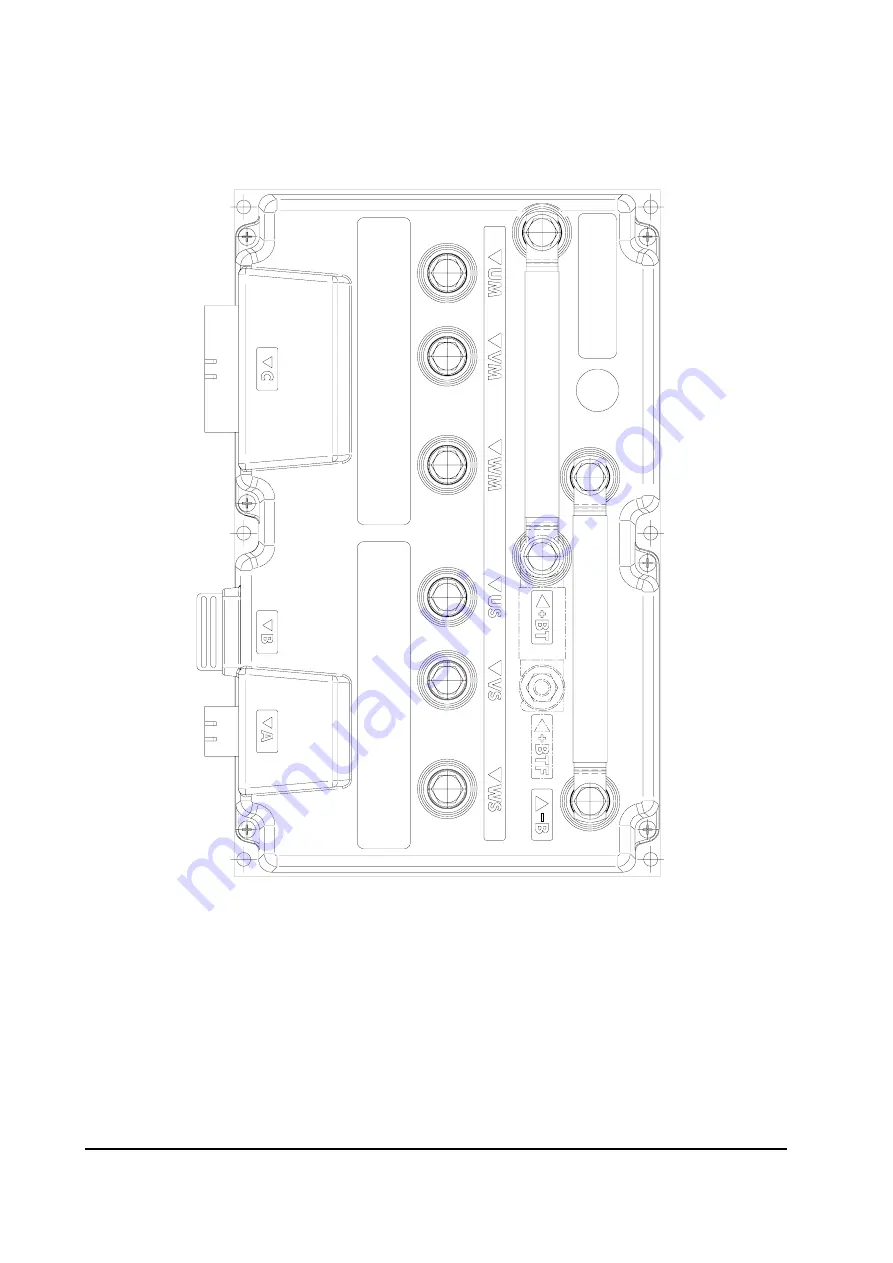
View of the power bars:

-B

Negative of the battery.

+BT

Positive of the battery; if the power fuse is not  present, the positive
cable coming from LC contact must be connected to this power
connection.

+BTF

Positive of battery before power fuse, must be connected to positive
cable coming from LC contact.

Um; Vm; Wm

Connection bars of the three right motors phases; follow this se-
quence and the indication on the motor.

Us; Vs; Ws

Connection bars of the three left motors phases; follow this se-
quence and the indication on the motor.

Summary of Contents for DUALAC2

Page 1: ...ndemergencyswitch 15 3 Safety and protection 16 4 Installation 17 4 1 Connectioncables 17 4 2 Contactors 17 4 3 Fuses 17 4 4 Description of connectors Dualac2 and Dualac2 Power 18 4 5 Description of c...

Page 2: ...ng see 5 5 60 5 6 3 Dualac2 and Dualac2 Power Tester user can verify the state of the followingparameters 60 5 6 4 Dualac2 hp and Dualac2 hp Power Tester user can verify the state ofthefollowingparame...

Page 3: ...RT MANAGER Publications N AE9ZP0BA Edition March 2003 7 Dualac2 and Dualac2 hp Inverter diagnostic 72 7 1 Traction related fault codes 72 7 2 Analysis of traction related alarms displayed on console 7...

Page 4: ...suitable for control of pairs of 3 0kW to 7 0kW motors The DUALAC2 HP can also control a DC Series pump motor up to 15kW These controllers have been expressly designed for battery powered applica tio...

Page 5: ...Digital control based upon a microcontroller one per each motor Voltage 24 36 48 72 80V Maximumcurrent 24V 350A RMS for 3 per each motor Maximumcurrent 36 48V 275A RMS for 3 per each motor Maximumcur...

Page 6: ...e per each AC motor Voltage 24 36 48 72 80V Maximumcurrent 24V 350A RMS for 3 per each motor Maximumcurrent 36 48V 275A RMS for 3 per each motor Maximumcurrent 72 80V 200A RMS for 2 per each motor Cho...

Page 7: ...ntrol based upon a microcontroller one per each AC motor Voltage 24 36 48 72 80V Maximumcurrent 24V 450A RMS for 3 per each motor Maximumcurrent 36 48V 350A RMS for 3 per each motor Maximumcurrent 72...

Page 8: ...turerange 30 C 40 C Maximuminvertertemperature atfullpower 75 C BLOCK DIAGRAM See chapter 2 2 Block Diagram 2 5 CONTROL UNIT 2 5 1 Microswitches The microswitches must have a contact resistance lower...

Page 9: ...close 0 represents the mechanical zero of the rotation The Left Hand graph shows the relationship of the motor voltage without signal acquisition being made The Right Hand Graph shows the same relatio...

Page 10: ...ng characteristics resistance in the 2kohm to 20kohm range suggested rotation electric angle at least 300 positive supply 5V or 10V potentiometer has to be installed in a way that in the zero position...

Page 11: ...tables are provided Option 1 tables for 3 wheels trucks with driving wheels counter rotation the internal wheelinvertsthedirection Option 2 tables for 4 wheels trucks without driving wheels counter ro...

Page 12: ...degree of protectionmeetingIP54 Protection against uncontrolled movements The main contactor will not close if ThePowerunitisnotfunctioning The Logic is not functioning perfectly the output voltage o...

Page 13: ...y an analog input so that a proportional brake feature is obtained Optimum sensitivity at low speeds Voltage boost at the start and with overload to obtain more torque with current control The inverte...

Page 14: ...material and system should be sized on the performance requirement of the machine Abnormal ambient air temperatures should be considered In situations where either ventilation is poor or heat exchang...

Page 15: ...is EN50081 2 2 12 MAIN CONTACTOR AND EMERGENCY SWITCH The connection of the battery line switches must be carried out following ZAPI instruc tions If a mechanical battery line switch is installed it i...

Page 16: ...input through two hardware independent circuits to both microcontrollerswhichimplementacross checkoftheinputstatus thuspreventingan abnormal behaviour due to a failure in the input hardware It is str...

Page 17: ...tery use cables having section of 35 mm as a minimum For the optimum inverter performance the cables to the battery should be run side by side and be as short as possible 4 2 CONTACTORS The main conta...

Page 18: ...on resistance A5 CANT_L CANBUStermination output 120ohminternallyconnectedto CAN_L Connect to CAN_H_OUT to insert the termination A6 CAN_L Low level CANBUS A7 CAN_H_OUT High level CANBUS to be used as...

Page 19: ...iometer BATT C16 PPOTST Positive of steering potentiometer 5V 12V C17 CPOTST Steering potentiometer wiper signal C18 CPOTB Brake potentiometer wiper signal C19 NPOTB BATT C20 NPOT Negative of traction...

Page 20: ...ation resistance A5 CANT_L CANBUStermination output 120ohminternallyconnectedto CAN_L Connect to CAN_H_OUT to insert the termination A6 CAN_L Low level CANBUS A7 CAN_H_OUT High level CANBUS to be used...

Page 21: ...iometer BATT C16 PPOTST Positive of steering potentiometer 5V 12V C17 CPOTST Steering potentiometer wiper signal C18 CPOTB Brake potentiometer wiper signal C19 NPOTB BATT C20 NPOT Negative of traction...

Page 22: ...vehigh D5 CMM Commonoutputofmicroswitches BATT D6 5TH Fifthhydraulicspeedinput activehigh D7 4TH Fourthhydraulicspeedinput activehigh D8 3RD Thirdhydraulicspeedinput activehigh D9 CPOTLIFT Inputforpro...

Page 23: ...ave different electronicoutput C11 C1 5V 12V positive of encoder power supply C12 C2 GND negative of encoder power supply C22 C13 A phase A of encoder C23 C14 B phase B of encoder 2 Connection of enco...

Page 24: ...rs is based on the canbus as well Dualac2 also provides built in can termination resistance which can be connected in different ways as described here following 4 7 1 Dualac2 Controller in stand alone...

Page 25: ...Page 25 4 7 3 Dualac2 Controller is a repetition module in the canbus net The canbus built in termination resistances are not inserted...

Page 26: ...ing from LC contact must be connected to this power connection BTF Positive of battery before power fuse must be connected to positive cable coming from LC contact Um Vm Wm Connection bars of the thre...

Page 27: ...tact must be connected to this power connection BTF Positive of battery before power fuse must be connected to positive cable coming from LC contact Um Vm Wm Connection bars of the three right motors...

Page 28: ...4 8 3 Dualac2 hp View of the power bars B Negativeofthebattery BT Positive of the battery if the power fuse is not present the positive cable coming from LC contact must be connected to this power con...

Page 29: ...bars of the three left motors phases follow this se quence and the indication on the motor P Outputofpumpmotorchopper P Pump chopper positive if the power fuse is not present the positive cable coming...

Page 30: ...4 Dualac2 hp Power View of the power bars B Negativeofthebattery BT Positive of the battery if the power fuse is not present the positive cable coming from LC contact must be connected to this power...

Page 31: ...bars of the three left motors phases follow this se quence and the indication on the motor P Outputofpumpmotorchopper P Pump chopper positive if the power fuse is not present the positive cable coming...

Page 32: ...Page 32 4 9 MECHANICAL DRAWING Dimensions of Dualac2...

Page 33: ...Page 33 Dimensions of Dualac2 Power...

Page 34: ...Page 34 Dimensions of Dualac2 hp...

Page 35: ...Page 35 Dimensions of Dualac2 hp Power...

Page 36: ...Page 36 4 10 CONNECTION DRAWING DUALAC2 AND DUALAC2 POWER STANDALONE...

Page 37: ...Page 37 4 11 CONNECTION DRAWING DUALAC2 HP AND DUALAC2 HP POWER STANDALONE...

Page 38: ...s and changes to the inverter s configuration are made using the Digital Console The Console is connected to the B connector of the inverter 5 2 DESCRIPTION OF CONSOLE CONNECTION Digital consoles used...

Page 39: ...Page 39 5 3 DESCRIPTION OF STANDARD CONSOLE MENU 5 3 1 Dualac2 and Dualac2 Power menu configuration 5 3 1 a Master...

Page 40: ...Page 40 5 3 1 b Slave...

Page 41: ...Page 41 5 3 2 Dualac2 hp and Dualac2 hp Power menu configuration 5 3 2 a Master...

Page 42: ...Page 42 5 3 2 b Slave...

Page 43: ...m current is reduced to the half of the programmed value OFF the battery discharge level check is carried out but no alarm is signalled 3 HYDROKEYON ON OFF if this option is programmed ON the traction...

Page 44: ...ERATURE DIGITAL a digital ON OFF motor thermal sensor is connected to C25 C35 input ANALOG an analog motor thermal sensor is connected to C25 C35 the curve can be customized on a customer request NONE...

Page 45: ...r sets the max steering angle in right direction 9 SET STEER LEFT this parameter sets the max steering angle in left direction 10 THROTTLE0ZONE establishes a deadband in the accelerator input curve se...

Page 46: ...output C28 5 4 2 Dualac2 and Dualac2 Power Slave Using the config menu of the programming console the user can configure the follow ingfunctions SUBMENU SETOPTIONS Notavailable SUBMENU ADJUSTEMENT 1...

Page 47: ...er Press ENTER pull the lever till the lift switch closes thenrecordthevalue OUT ENTER 4 SET ACCELER MAX This parameter is used to adjust maximum value of the lift potentiometer Press ENTER pull the l...

Page 48: ...NTER to go into the SET MODEL Menu 7 ThedisplaywillshowsthefirstOPTION 8 Press ROLL UP or ROLL DOWN button until desired OPTION appears 9 Desired OPTION appears 10 Press SET UP or SET DOWN button in o...

Page 49: ...DJUSTMENTSMenuappears 5 ADJUSTMENTS appears on the display 6 Press ENTER to go into the ADJUSTMENTS Menu 7 ThedisplaywillshowsSETBATTERYTYPE 8 Press ROLL UP or ROLL DOWN button until the desired param...

Page 50: ...TMENTS appears on the display 6 Press ENTER to go into the ADJUSTMENTS Menu and use ROLL UP DOWN buttons to final theSETBATTERYTYPEparameter 7 Thedisplaywillshow SETBATTERYTYPE 8 Press SET UP to choos...

Page 51: ...u 7 The display will show the first OPTION 8 Press ROLL UP or ROLL DOWN button until desired OPTION appears 9 ADJUST BATTERY appears 10 Press SET UP or SET DOWN button in order to increase or decrease...

Page 52: ...imum speed in forward direction 8 MAX SPEED BACKWARD determines the maximum speed in backward direction 9 CURVE CUTBACK Speed reduction when the truck is doing a curve The parameter sets the speed set...

Page 53: ...50 63 75 87 100 CUTBACK SPEED 10 15 20 25 38 50 63 75 87 100 FREQUENCY CREEP Hz 0 3 0 6 0 9 1 2 1 5 1 8 2 1 2 4 2 7 3 MAXIMUM CURRENT IMAX 43 50 56 62 68 75 81 87 94 100 AUXILIARY TIME Sec 0 0 2 0 4 0...

Page 54: ...in forward direction 8 MAX SPEED BACKWARD determines the maximum speed in backward direction 9 CURVE CUTBACK Speed reduction when the truck is doing a curve The parameter sets the speed setpoint when...

Page 55: ...om 0 Hz to 100 Hz This is the ideal ramp calculated by the software the real ramp could change as a function of motor control parameter setting and obviously as a function of the load The braking feat...

Page 56: ...is a function of the motor current Aim of this function is to reduce as for as possible the speed change when the motor is loaded Increasing the parameter the V is increased 9 2ND SPEED COMP this par...

Page 57: ...otor current Aim of this function is to reduce as for as possible the speed change when the motor is loaded Increasing the parameter the V is increased 15 5TH SPEED COMP this parameter sets the voltag...

Page 58: ...EED FINE 0 100 3RD SPEED COMP 0 100 4TH SPEED FINE 0 100 4TH SPEED COMP 0 100 5TH SPEED FINE 0 100 5TH SPEED COMP 0 100 HYDRO SPEED FINE 0 100 HYDRO SPEED COMP 0 100 HYDRO TIME Sec 0 25 5 PUMP IMAX IM...

Page 59: ...ss ENTER to go into the ParameterChangefacility 5 The Display will show the first parameter 6 Press either ROLL UP and ROLL DOWN to display the next parameter 7 The names of the Parameters appear on t...

Page 60: ...der Hz slipvalue Hz slipvalue Hz currentrms A currentrms A temperature C temperature C temperature 1 C seatswitch ON OFF temperature 2 C forw switch ON OFF accelerator V back switch ON OFF steer angle...

Page 61: ...ch ON OFF 3rd speed switch ON OFF enableswitch ON OFF 4th speed switch ON OFF brakeswitch ON OFF 5th speed switch ON OFF cutbackswitch ON OFF pumpcurrent A exclusivehydro ON OFF pumpvmn V handbrake ON...

Page 62: ...able on Chapter 4 5 4 6 8 Set the Acceleration Delay requirements for the machine Test the parameter setting in bothdirections 9 Set the FREQUENCY CREEP level starting from level 0 6 Hz The machine sh...

Page 63: ...y 5 CURRENT RMS Root Mean Square value of the motor current 6 TEMPERATURE the temperature measured on the aluminum heat sink holding the MOSFET devices 7 TEMPERATURE 1 this is the temperature of the r...

Page 64: ...or in load condition it is expressed in a percentage of the full voltage 22 BATTERY VOLTAGE level of battery voltage measured at the input of the key switch 23 BATTERY CHARGE the percentage Charge lev...

Page 65: ...4 SLIP VALUE this is the difference of speed between the rotating field and the shaft of the motor expressed in the same unit of the frequency 5 CURRENT RMS Root Mean Square value of the motor curren...

Page 66: ...active switch opened OFF VB input non active switch closed 21 VOLTAGE BOOSTER this is the booster of the voltage supplied to the motor in load condition it is expressed in a percentage of the full vol...

Page 67: ...draulic system ON VB input active switch closed OFF GND input non active switch open 14 2 ND SPEED SWITCH status of the second speed switch of the hydraulic system ON VB input active switch closed OFF...

Page 68: ...3 The Display will show 4 Press ROLL UP or ROLL DOWN button until TESTER MENU appear on the display 5 The Display shows 6 Press ENTER to go into the TESTER function 7 The first variable to be tested...

Page 69: ...oller set of parameters can be retained in a Pc and downloadedtoanothercontroller seeRESTORE RESTORE function allows to download controller parameters from the Pc console memory to the controller Eepr...

Page 70: ...Opening Zapi Display 2 Press ENTER to go into the General menu 3 The Display will show 4 Press ROLL UP or ROLL DOWN button until PARAMETER CHANGE appears on the display 5 TheDisplaywillshow 6 Press EN...

Page 71: ...tton until PROGRAM VACC appears on the display 5 The Display will show 6 Press ENTER to go into the PROGRAM VACC routine 7 The Display will show the minimum and maximum valuesofpotentiometerwiperoutpu...

Page 72: ...W voltage feedback circuit To remove alarm condition activation of traction request 19 LOGIC FAILURE 1 X X X X Alarm an overvoltage or undervolt condition has been detected To recycle the key switch...

Page 73: ...ntactor coil driver is shorted If the alarm is present in Init status remove the alarm cause If the alarm has occurred in stby or running mode it is necessary to remove alarm cause and to activate tra...

Page 74: ...ause and activate a traction request 245 WRONG SET BA TTERY X X Alarm the battery voltage does not correspond to SET BA TTERY programmation To remove alarm cause 246 SLA VE KO X X X X Alarm Master C d...

Page 75: ...igher than V ACC MIN 1V while the traction enable switch is open To remove Warning cause 79 INCORRECT START X X X X Warning wrong traction request sequence To remove Warning cause 80 FORWARD BACKWARD...

Page 76: ...he hardware section of the logic board which manages the overvoltage protection Replace the logic card 5 VMNLOW VMNHIGH The test is carried out during initial diagnosis and in standby Possible causes...

Page 77: ...tion logic closes the LC and checks the voltage on the Drain of the driver If this is not low the driver is not able to close an alarm is signalled Replace the logic CONTACTOR OPEN The main contactor...

Page 78: ...s SLAVE C malfunctioning it brings the controller in a safe status opening the power bridge and the Line Contactor 14 MASTER KO Slave and Master Cs perform a cross check in order to verify their funct...

Page 79: ...f level If it happens when the motor is cold check the wiring If all is ok replace the logic board 20 BATTERYLOW If the battery check option is ON a battery discharge algorithm is carried out When the...

Page 80: ...tected a fault condition the Slave is aware of this thanks to canbus communication it cannot drive the motor until the Master has resolved its problem The fault has to be looked for in the Master 27 N...

Page 81: ...PWM applied to pump chopper the pump current sensor feedback is out of the zero current window If the alarm is present in Init status remove the alarm cause If the alarm has occurred in stby or runnin...

Page 82: ...uit dispersion in the pump motor to truck frame 2 PUMPSTBYIHIGH The pump chopper current sensor feedback is out of the zero current window while no PWM is applied to the pump chopper The most likely c...

Page 83: ...Part Number Description C16507 Protected 500A strip Fuse C16505 Protected 355A strip Fuse C16520 6 3A 20mm Control Circuit Fuse C29523 SW 180 80V Single Pole Contactor C29522 SW 180 48V Single Pole Co...

Page 84: ...level Check every 3 months Check the mechanical operation of the Contactor s Moving contacts should be free to movewithoutrestriction Check every 3 months Checks should be carried out by qualified pe...

Page 85: ...DUALAC2INVERTER OPERATINGHANDBOOK ANDFUNCTIONDESCRIPTION ELECTRONICINDUSTRIALDEVICES 42028 POVIGLIO R E Via Parma 59 ITALIA Tel 39 0522 960050 r a Fax 39 0522 960259 e mail zapi zapispa it...

Reviews: