SECTION 3 - HANDLING, STORAGE, INSTALLATION AND REASSEMBLY
FORM 155.32-ICOM2.EN.UL
ISSUE DATE:1/10/2018
34
JOHNSON CONTROLS
• An oil level control device and an oil level alarm device should be installed at the oil
service tank to prevent accidents such as oil leakage.
• Adequate flushing of the connection piping should be performed.
• During commissioning, be sure to purge air from the oil pump.
• Prevent foreign materials such as water, sludge, or other materials from entering into
the oil tank piping. If water, sludge, or other materials enter the oil piping, it may cause
incomplete combustion of the burner.
• When the temperature at the fuel tank or oil delivery line becomes below 32°F, fluidity
of the fuel may drop and cause generation of soot or flame failure due to insufficient
combustion. A band heater should be installed, depending on insulation and the other
circumstances, so that temperature of the fuel tank and the oil delivery line is main-
tained at above 32°F.
• Since static electricity may stay at the oil piping and the oil tank, those parts should be
grounded with a metallic conductor to remove the static electricity.
• Cleaning the furnace and gas duct at fixed intervals is necessary.
FLUE EQUIPMENT PROCEDURE
Select a flue material having sufficient corrosion resistance. Provide the flue with heat
insulation to prevent burns and ambient temperature rises.
Design a flue that makes the static pressure 0 to -49 Pa at the high-temperature generator
connection to the flue. It is recommended that two or more flues, a draft regulator for
stabilizing combustion, and a fixed damper for adjusting ventilation force be installed. If
more than one chiller-heater is installed or a chiller-heater is installed side by side with a
boiler, etc., provide the chillers with separate flues to prevent the back flow of exhaust gas
to the machine that is not operating.
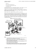
When installing an assembly gas duct unavoidably, design one which makes the exhaust
gas pressure 0 to -49 Pa at each machine connection with the flue. In addition, connect the
flue junctions at an angle of 45°F, or less or install a rectifier plate to prevent the mutual
interference of exhaust gas from the individual flues, see
. The flue
should be free of sharp bends or a sharp change in passage area. Make the bends gentle
and install a guide plate as required.
When the chiller-heater is installed side by side with a machine which has a different
combustion system (e.g., diesel engine), provide the chiller-heaters with separate flues to
ensure stable combustion and prevent oscillating combustion.
When a flue damper is installed, provide the damper with a limit switch for confirming “full
open” of the damper in order to prevent explosions. In addition, secure the interlock which
prevents the chiller-heater from being started with the damper kept closed (see the
procedural drawing for sequential operation).
The flues should be as short as possible. In particular, the horizontal flue led from the
chiller-heater outlet should be as short as possible in order to prevent a decline in
ventilation force (preferably, within 1 m from the machine base). In this case, make the flue
rise 2 m or more and then secure it in the horizontal position. If the horizontal section of the
flue is too long, it can cause unstable and/or oscillating combustion.
Install the following devices to the flue:
• Mount for thermometer which measures flue gas temperature
T
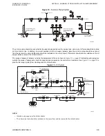
he oil service tank shall be installed in such a way that oil supply pressure at the oil
input of the fuel oil burning pump is not less than 0
MM
H
G
and not more than
368mmHg.

