


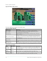


Variable speed drive (VSD) details screen
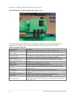
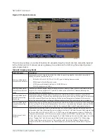
Figure 31: Variable speed drive (VSD) details screen
This screen displays more detailed information about the variable speed drives (VSDs). There are
two separate screens: one for VSD 1 and one for VSD 2. However, the information is similar.
Table 74: Display only fields
Field/LED name
Description
Motor run (LED)
Indicates whether the digital output from the controls is commanding the motor to
RUN.
% Full Load Amps
Displays the motor current as a percentage of the Full Load Amps (FLA) value. For the
Variable Speed Drive, this is the data returned by the VSD Logic Board.
Motor current limit setpoint
Displays the current limit value in use. This value could come from a 0 mA to 20 mA, 4
mA to 20 mA, 0 VDC to 10 VDC, or 2 VDC to 10 VDC input in Analog Remote mode, PWM
signal in Digital Remote mode, SC-EQ communications interface in ISN (BAS) mode, or
a locally programmed value.
Pulldown demand time left
Displays the time remaining in the programmed pulldown period if the value is
nonzero.
Full load amps
Displays the Full Load Amps value as reported by the VSD.
VSD model
Displays the VSD model as reported by the VSD.
Water pump output (LED)
Indicates whether the relay controlling the water pump output is energized.
Precharge relay output (LED)
Indicates whether the relay controlling the precharge output is energized.
Trigger SCR output (LED)
Indicates whether the relay controlling the Trigger SCR Output is energized.
DC bus voltage
Displays the DC Bus voltage as reported by the VSD.
DC inverter link current
Displays the DC Inverter link current as reported by the VSD.
Internal ambient temperature
Displays the ambient temperature inside the VSD cabinet as reported by the VSD.
Converter heatsink temperature
Displays the heatsink temperature of the converter as reported by the VSD.
Heatsink temperature
Displays the baseplate temperatures of the 3 phases of the VSD inverter as reported
by the VSD.
Programmable
None
Model YD Mod D with OptiView Control Center
84
Summary of Contents for YD Mod D
Page 2: ...2 Model YD Mod D with OptiView Control Center...
Page 8: ...Nomenclature Model YD Mod D with OptiView Control Center 8...
Page 17: ...Figure 2 Chiller operation flow chart 17 Model YD Mod D with OptiView Control Center...
Page 18: ...Figure 2 Chiller operation flow chart Model YD Mod D with OptiView Control Center 18...
Page 19: ...Figure 2 Chiller operation flow chart 19 Model YD Mod D with OptiView Control Center...
Page 20: ...Figure 2 Chiller operation flow chart Model YD Mod D with OptiView Control Center 20...
Page 21: ...Figure 2 Chiller operation flow chart 21 Model YD Mod D with OptiView Control Center...
Page 22: ...Figure 2 Chiller operation flow chart Model YD Mod D with OptiView Control Center 22...
Page 150: ...Figure 57 Sample printout status Model YD Mod D with OptiView Control Center 150...
Page 151: ...Figure 57 Sample printout status 151 Model YD Mod D with OptiView Control Center...
Page 152: ...Figure 58 Sample printout setpoints Model YD Mod D with OptiView Control Center 152...
Page 153: ...Figure 58 Sample printout setpoints 153 Model YD Mod D with OptiView Control Center...
Page 154: ...Figure 59 Sample printout schedule Model YD Mod D with OptiView Control Center 154...
Page 155: ...Figure 60 Sample printout sales order 155 Model YD Mod D with OptiView Control Center...
Page 156: ...Figure 61 Sample printout history Model YD Mod D with OptiView Control Center 156...
Page 157: ...Figure 61 Sample printout history 157 Model YD Mod D with OptiView Control Center...
Page 159: ...Figure 64 Sample printout custom screen report 159 Model YD Mod D with OptiView Control Center...