


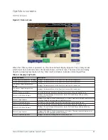


Refrigerant level control screen
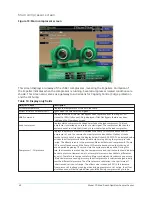
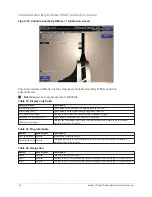
Figure 9: Refrigerant level control screen
This screen displays a cutaway view of the chiller condenser, along with the liquid refrigerant level
sensor and variable orifice. Setpoints relating to the liquid level control are maintained on this
screen. Through animation, the variable orifice position is displayed. Also, the refrigerant flow
control valve (variable orifice) can be manually operated. It is only accessible with a Service Level
Password.
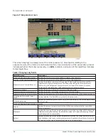
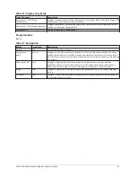
Table 13: Display only fields
Field/LED name
Description
Condenser refrigerant level
Displays the present position of the liquid level. The refrigerant level is animated in the
cutaway view of the condenser. When the actual level is 0% to 15%, the level is shown
as 50% full. When the actual level is16% to 31%, the level is shown as 60% full. When
the actual level is 32% to 47%, the level is shown as 70% full. When the actual level is
48% to 63%, the level is shown as 80% full. When the actual level is 64% to 79%, the
level is shown as 90% full. Actual levels above 79%, are shown as 100% full.
Note:
Requires a logon access level of Service.
Subcooler effectiveness
The Subcooler Effectiveness is evaluated with the following calculation and compared
to a high and low limit. (Cond Sat Temp-Drop Leg Ref Temp)/(Cond Sat Temp-Entering
Cond Liq Temp). This value is typically near 0.8 at design conditions.
Level control state
Indicates one of the following states the level control routine is in: Manual, Inactive,
Startup Hold, Setpoint Ramp, PID Control, Hold.
Startup delay remaining
The level valve is held at the starting position until 15 seconds after start to allow the
system to stabilize. Then the valve position is controlled by the PID loop. This read box
displays the remaining seconds until PID control.
Level control valve command
Indicates the valve command as a percentage of full open. It is only displayed when
the valve control method is analog.
Model YD Mod D with OptiView Control Center
38
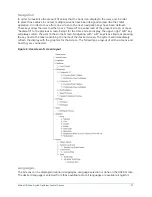
Summary of Contents for YD Mod D
Page 2: ...2 Model YD Mod D with OptiView Control Center...
Page 8: ...Nomenclature Model YD Mod D with OptiView Control Center 8...
Page 17: ...Figure 2 Chiller operation flow chart 17 Model YD Mod D with OptiView Control Center...
Page 18: ...Figure 2 Chiller operation flow chart Model YD Mod D with OptiView Control Center 18...
Page 19: ...Figure 2 Chiller operation flow chart 19 Model YD Mod D with OptiView Control Center...
Page 20: ...Figure 2 Chiller operation flow chart Model YD Mod D with OptiView Control Center 20...
Page 21: ...Figure 2 Chiller operation flow chart 21 Model YD Mod D with OptiView Control Center...
Page 22: ...Figure 2 Chiller operation flow chart Model YD Mod D with OptiView Control Center 22...
Page 150: ...Figure 57 Sample printout status Model YD Mod D with OptiView Control Center 150...
Page 151: ...Figure 57 Sample printout status 151 Model YD Mod D with OptiView Control Center...
Page 152: ...Figure 58 Sample printout setpoints Model YD Mod D with OptiView Control Center 152...
Page 153: ...Figure 58 Sample printout setpoints 153 Model YD Mod D with OptiView Control Center...
Page 154: ...Figure 59 Sample printout schedule Model YD Mod D with OptiView Control Center 154...
Page 155: ...Figure 60 Sample printout sales order 155 Model YD Mod D with OptiView Control Center...
Page 156: ...Figure 61 Sample printout history Model YD Mod D with OptiView Control Center 156...
Page 157: ...Figure 61 Sample printout history 157 Model YD Mod D with OptiView Control Center...
Page 159: ...Figure 64 Sample printout custom screen report 159 Model YD Mod D with OptiView Control Center...