York YD A Operating & Maintenance Download Page 45

JOHNSON CONTROLS

45

SECTION 6 – MAINTENANCE

FORM 160.69-O2 

ISSUE DATE: 9/30/2020

6

CONDENSERS AND EVAPORATORS
GENERAL

Maintenance of condenser and evaporator shells is im-

portant to provide trouble free operation of the chiller. 

The water side of the tubes in the shell must be kept 

clean and free from scale. Proper maintenance such as 

tube cleaning, and testing for leaks, is covered on the 

following pages.

CHEMICAL WATER TREATMENT

Since the mineral content of the water circulated 

through evaporators and condensers varies with almost 

every source of supply, it is possible that the water be-

ing used may corrode the tubes or deposit heat resistant 

scale in them. Reliable water treatment companies are 

available in most larger cities to supply a water treat-

ing process which will greatly reduce the corrosive and 

scale forming properties of almost any type of water.
As a preventive measure against scale and corrosion 

and to prolong the life of evaporator and condenser 

tubes, a chemical analysis of the water should be made 

preferably before the system is installed. A reliable wa-

ter treatment company can be consulted to determine 

whether water treatment is necessary, and if so, to fur-

nish the proper treatment for the particular water con-

dition.

CLEANING EVAPORATOR AND CONDENSER 

TUBES
Evaporator

It is difficult to determine by any particular test wheth-

er possible lack of performance of the water evaporator 

is due to fouled tubes alone or due to a combination 

of troubles. Trouble which may be due to fouled tubes 

is indicated when, over a period of time, the cooling 

capacity decreases and the split (temperature differ-

ence between water leaving the evaporator and the 

refrigerant temperature in the evaporator) increases. A 

gradual drop-off in cooling capacity can also be caused 

by a gradual leak of refrigerant from the system or by a 

combination of fouled tubes and shortage of refrigerant 

charge. An excessive quantity of oil in the evaporator 

can also contribute to erratic performance.

Condenser

In a condenser, trouble due to fouled tubes is usually 

indicated by a steady rise in head pressure, over a pe-

riod of time, accompanied by a steady rise in condens-

ing temperature, and noisy operation. These symptoms 

may also be due to foul gas buildup. Purging will re-

move the foul gas revealing the effect of fouling.

TUBE FOULING

Fouling of the tubes can be due to deposits of two types 

as follows:

1. 

Rust or sludge

  –  which  finds  its  way  into  the 

tubes and accumulates there. This material usu-

ally does not build up on the inner tube surfaces 

as scale, but does interfere with the heat transfer. 

Rust or sludge can generally be removed from the 

tubes by a thorough brushing process.

2. 

Scale

 – due to mineral deposits. These deposits, 

even though very thin and scarcely detectable 

upon physical inspection, are highly resistant to 

heat  transfer.  They  can  be  removed  most  effec

-

tively by circulating an acid solution through the 

tubes.

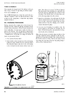
TUBE CLEANING PROCEDURES
Brush Cleaning of Tubes

If the tube consists of dirt and sludge, it can usually be 

removed by means of the brushing process. Drain the 

water sides of the circuit to be cleaned (cooling wa-

ter or chilled water) remove the heads and thorough-

ly clean each tube with a soft bristle bronze or nylon 

brush. 

DO NOT USE A STEEL BRISTLE BRUSH

A steel brush may damage the tubes.
Improved results can be obtained by admitting water 

into the tube during the cleaning process. This can be 

done by mounting the brush on a suitable length of 1/8" 

pipe with a few small holes at the brush end and con-

necting the other end by means of a hose to the water 

supply.
The tubes should always be brush cleaned before acid 

cleaning.

Summary of Contents for YD A

Page 1: ...MODEL YD STYLE A B WITH OPTIVIEW CONTROL CENTER AND ELECTRO MECHANICAL STARTER COOLING ONLY CENTRIFUGAL LIQUID CHILLERS OPERATING MAINTENANCE Supersedes 160 69 O2 912 Form 160 69 O2 920 Issue Date Sep...

Page 2: ...ls This individual shall also be familiar with and comply with all applicable governmental standards and regulations pertaining to the task in question SAFETY SYMBOLS The following symbols are used in...

Page 3: ...equipment If there is any question regarding the applicability of these documents rig ging lifting and operating service personnel should verify whether the equipment has been modified and if current...

Page 4: ...W CB 5CX DA 5DA DB 5DB DC 5DC DE 5DE DF 5DF DG 5DG DH 5DH DJ 5DJ DK 5DK DL 5DL NOMENCLATURE YD XF XA J2 CA A B or C POWERSUPPLY for 60 Hz 5 for 50 Hz DESIGN LEVEL MODEL CONDENSER CODE XA XB XC XD YA Y...

Page 5: ...System 27 Prolonged Shutdown 27 SECTION 3 SYSTEM COMPONENTS DESCRIPTION 29 General 29 Compressor 29 Capacity Control 29 Compressor Lubrication System 29 Oil Pump 30 Oil Heater 32 Motor Driveline 32 H...

Page 6: ...ing 45 Tube Cleaning Procedures 45 Acid Cleaning Of Tubes 46 Commercial Acid Cleaning 46 Testing For Evaporator And Condenser Tube Leaks 46 Compressor 47 Electrical Controls 47 SECTION 7 PREVENTIVE MA...

Page 7: ...GURE 6 Schematic Drawing YD Compressor Lubrication System 31 FIGURE 7 Oil Return System 35 FIGURE 8 Charging Oil Reservoir With Oil 36 FIGURE 9 Evacuation Of Chiller 39 FIGURE 10 Saturation Curve 41 F...

Page 8: ...JOHNSON CONTROLS 8 FORM 160 69 O2 ISSUE DATE 9 30 2020 THIS PAGE INTENTIONALLY LEFT BLANK...

Page 9: ...y is equipped with a potentiometer to provide vane posi tion A calibration procedure assures displayed posi tion accuracy The vanes can be manually controlled Each compressor also has a Discharge Temp...

Page 10: ...features are detailed separately be low If equipped with the compressor Variable Geometry Diffuser VGD the chiller is started with the VGD in the fully open position Upon receipt of a chiller start s...

Page 11: ...llow Lead motor current Meanwhile the Lead compressor Pre rotation Vanes have been modulated to maintain the Leaving Chilled Liquid Temperature setpoint unless Lag Start with High Head was performed W...

Page 12: ...Con trol Valve while bringing on the Lead compressor It displays Lag Start when performing the Refrigerant Level Control Lag Start mode while starting the Lag compressor The Override Time Remaining d...

Page 13: ...lowed to operate all the way up to its full load amps of 800 Amps because the total chiller current is being limited to 1120 Amps Compressor Lockout The COMPRESSOR LOCKOUT Setpoint available on the Ca...

Page 14: ...e rotation Vanes are driven closed When the Vanes have fully closed or 210 seconds have elapsed whichever occurs first the Discharge Valve is then driven closed When the Discharge Valve has fully clos...

Page 15: ...or Discharge Valve Electro Mechanical Starter Chiller Start Sequence Auto zero the 3 Oil Pressure Transducers Pre Lube cycle Lead Compressor Normal Sequence Extended prelube switch applies only to lea...

Page 16: ...oint Timer Is Lag Compressor Ready to Start Yes Yes Yes NO No No Pre Lube Lag Oil Pump Don t auto zero oil pressure transducers No No 2n Trend rate of pull down on startup to decide on d compr Antirec...

Page 17: ...ontrol Lag Compr PRVs are controlled to follow motor current of Lead System Run Two Compressors 40 Seconds Alarm Fault No Delay 50 seconds To allow motor starting transition time Are Motor Currents Eq...

Page 18: ...Lag Compressor Discharge Valve Lag Compr Disch Valve Closed Stop Lag Compressor Motor Drive Lag Compressor vanes closed Post Lube Run Time Lag Compressor Yes No Yes 1 Compr Running Restart 2nd compr i...

Page 19: ...lves on both compressors Stop both compressor motors Post Lube Run time both compr oil pumps Energize Oil Heater 1 Compressor Running from Page 1 or 4 Chiller normal or cycling stop signal Stop Lead c...

Page 20: ...ult Stop manual or auto restart Stop both compressors simultaneously Chiller Fault Condition Post Lube Run time both compr oil pumps Energize Oil Heater 1 Compressor Running from Page 1 or 4 Chiller F...

Page 21: ...ng LChWT Lag Compressor following current of Lead No Yes No Yes Close Compressor Pre rotation Vane Motors No Have of Total Surge Counts Exceeded the allowed within time period setting Stop and Lockout...

Page 22: ...JOHNSON CONTROLS 22 FORM 160 69 O2 ISSUE DATE 9 30 2020 THIS PAGE INTENTIONALLY LEFT BLANK...

Page 23: ...IR Proper operating oil level During operation the oil level should fall to the Operating Range identified on the vertical oil level indicator label See Figure 3 on page 23 If the oil level during ope...

Page 24: ...initiated and will run for 30 minutes after the compressor starts If the chiller shuts down during this period of time it cannot be started until the timer completes the 30 minute cycle 4 The chilled...

Page 25: ...hilled water temperature Cooling tower fan cycling will normally provide adequate control of the entering condenser water temperature on most instal lations OPERATING LOG SHEET A permanent daily recor...

Page 26: ...procedure the operator will avoid serious operating difficulty The following list of inspections and procedures should be used as a guide Daily 1 Check OptiView Control Center displays 2 If the compre...

Page 27: ...eously with the oil pump The actual water pump con tact operation is dependent upon the position of Microboard jumper J54 3 Open the switch to the cooling tower fan motors if used 4 The compressor sum...

Page 28: ...JOHNSON CONTROLS 28 FORM 160 69 O2 ISSUE DATE 9 30 2020 THIS PAGE INTENTIONALLY LEFT BLANK...

Page 29: ...ssor is able to handle the load more efficiently COMPRESSOR LUBRICATION SYSTEM The chiller lubrication system consists of the oil pump oil filter oil cooler and all interconnecting oil piping and pass...

Page 30: ...e oil pump should operate at all times during chiller operation On shutdown of the system for any reason the oil pump operates and continues to run for 150 seconds The system cannot restart during tha...

Page 31: ...NTROLS 31 SECTION 3 SYSTEM COMPONENTS DESCRIPTION FORM 160 69 O2 ISSUE DATE 9 30 2020 3 LOW SPEED GEAR REAR BEARING DOUBLE BELLOWS SHAFT SEAL Figure 6 SCHEMATIC DRAWING YD COMPRESSOR LUBRICATION SYSTE...

Page 32: ...ors or suction baffles are located above the tube bundle to prevent liquid refrig erant carryover into the compressor A 2 liquid level sight glass is located on the side of the shell to aid in determi...

Page 33: ...the refrigerant in this system must be performed by a qualified service technician OPTIONAL HOT GAS BYPASS Hot gas bypass is optional and is used to eliminate compressor surge during light load or hig...

Page 34: ...JOHNSON CONTROLS 34 FORM 160 69 O2 ISSUE DATE 9 30 2020 THIS PAGE INTENTIONALLY LEFT BLANK...

Page 35: ...To change the dehydrator use the following procedure 1 Shut the stop valves on the condenser gas line oil return line to rotor support and inlet end of the dehydrator 2 Remove the dehydrator Refer to...

Page 36: ...il and connect the pump discharge connection to the oil charging valve A located on the remote oil reservoir cover plate See Figure 8 on page 36 Do not tighten the connection at the charging valve unt...

Page 37: ...roblem Remove obstruction Temperature difference between leav ing chilled water and refrigerant in evaporator greater than normal with high discharge temperature Evaporator tubes dirty or restricted C...

Page 38: ...Inspect and replace worn parts Partially blocked oil supply inlet Check oil inlet for blockage SYMPTOM OIL PRESSURE GRADUALLY DECREASES NOTED BY OBSERVATION OF DAILY LOG SHEETS When oil pump VSD frequ...

Page 39: ...leaks too small to be found by the soap test To test with R 22 proceed as follows 1 With no pressure in the system charge R 22 gas into the system through the charging valve to a pressure of 2 PSIG 14...

Page 40: ...pressure of 5 mm Hg is reached See Table 2 on page 40 for corre sponding values of pressure 4 To improve evacuation circulate hot water not to exceed 125 F 51 7 C through the evaporator and condenser...

Page 41: ...n pressure tested and found to be tight prior to evacuation then the saturation tempera ture recordings should follow a curve similar to the typical saturation curve shown as Figure 10 on page 41 The...

Page 42: ...rant is connected or changed Refrigerant may be furnished in cylinders contain ing either 30 50 125 or 1750 lbs 207 345 862 or 12 066 kg of refrigerant R 134A EVAPORATOR CODE LBS KG S FB 11022 5000 FC...

Page 43: ...rigerant level should be observed and the level re corded after initial charging HANDLING REFRIGERANT FOR DISMANTLING AND REPAIRS If it becomes necessary to open any part of the refriger ant system fo...

Page 44: ...RM 160 69 O2 ISSUE DATE 9 30 2020 SECTION 6 MAINTENANCE LD00476 Figure 12 MOTOR STARTER TEMPERATURE AND INSULATION RESISTANCES Minimum Insulation Resistance vs Temperature per IEEE Std 43 Open Motors...

Page 45: ...radual drop off in cooling capacity can also be caused by a gradual leak of refrigerant from the system or by a combination of fouled tubes and shortage of refrigerant charge An excessive quantity of...

Page 46: ...ten at each section of tubes for a hissing sound that would indicate gas leakage This will assist in locating the section of tubes to be further investigated If the probable location of the leaky tube...

Page 47: ...passages or dirty oil fil ters If the unit is shutting down on HOT High Oil Temperature or Low Oil Pressure OP change the oil filter element Examine the oil filter element for the presence of aluminu...

Page 48: ...JOHNSON CONTROLS 48 FORM 160 69 O2 ISSUE DATE 9 30 2020 THIS PAGE INTENTIONALLY LEFT BLANK...

Page 49: ...tion Grease fittings are not supplied and bearings are designed for long life under standard conditions Frames 284T thru 587UZ are furnished with double shielded or open ball or roller bearings It is...

Page 50: ...e to the benefit of the user to provide for proper water treatment to provide for a longer and more economical life of the equipment The following recommendation should be followed in determining the...

Page 51: ...lsius multiply by 5 9 or 0 5556 Example 10 0 F range x 0 5556 5 6 C range Table 5 SI METRIC CONVERSION MEASUREMENT MULTIPLY ENGLISH UNIT BY FACTOR TO OBTAIN METRIC UNIT Capacity Tons Refrigerant Effec...

Page 52: ...ennsylvania USA 17349 1 800 524 1330 Subject to change without notice Printed in USA Copyright by Johnson Controls 2020 www johnsoncontrols com ALL RIGHTS RESERVED Form 160 69 O2 920 Issue Date Septem...

Reviews: