


JOHNSON CONTROLS
24
FORM 160.69-O2
ISSUE DATE: 9/30/2020
SECTION 2 – SYSTEM OPERATING PROCEDURES
START-UP
1. If the chilled water pump is manually operated,
start the pump. The Control Center will not al-
low the chiller to start unless chilled liquid flow
is established through the unit. (A field supplied
chilled water flow switch is required.) If the
chilled liquid pump is wired to the Microcom-
puter Control Center the pump will automatically
start, therefore, this step is not necessary.
2. To start the chiller, press the
COMPRESSOR
START
switch. This switch will automatically
spring return to the RUN position. (If the unit
was previously started, press the
STOP/RESET
side of the
COMPRESSOR
switch and then
press the
START
side of the switch to start the
chiller.) When the start switch is energized, the
Control Center is placed in an operating mode and
any malfunction will be noted by messages on a
graphic display.
Any malfunctions which occur during
STOP/RESET are also displayed.
When the chiller is shut down, the prerotation vanes
will close automatically to prevent loading the com-
pressor on start-up.
When the chiller starts to operate, the following auto-
matic sequences are initiated:
1. The OptiView™ Control Center display message
will read
SYSTEM PRELUBE
for the first 50
seconds of the starting sequence.
2. The oil pump will start to circulate oil for a
50 second pre-run to establish oil flow and
adequate lubrication to all bearings, gears,
and rotating surfaces within the compressor.
The high and low oil pressure transducers (OP)
and the oil temperature sensor (RT3) will sense
any malfunction in the lubrication system.
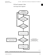
3. The anti-recycle timer (non-VSD Chillers only)
software function will operate after the 50 sec-
onds of pre-run time. At this time, the timer will
be initiated and will run for 30 minutes after the
compressor starts. If the chiller shuts down during
this period of time, it cannot be started until the
timer completes the 30 minute cycle.
4. The chilled liquid pump contacts will close, start-
ing the chilled liquid pump, to allow liquid flow
through the evaporator when the COMPRESSOR
start switch is energized.
5.
After the first 50 seconds of operation, the com
-
pressor will start.
6. For display messages and information pertaining
to the operation of the OptiView™ Control Cen-
ter,
refer to Form 160.69-O1
.
CHILLER OPERATION
After the compressor reaches its operating speed, the
Prerotation Vanes will begin to open under the control
of the Microprocessor Board which senses the leav-
ing chilled liquid temperature. The unit capacity will
vary to maintain the leaving
CHILLED LIQUID
TEMPERATURE
setpoint. The Prerotation Vanes are
modulated by an actuator under the control of the Mi-
croprocessor Board. The vane control routine employs
proportional plus derivative (rate) control action. A
drop in chilled liquid temperature will cause the actua-
tor to close the Prerotation Vanes to decrease chiller
capacity. When the chilled liquid temperature rises, the
actuator will open the Prerotation Vanes to increase the
capacity of the chiller.
However, the current draw (amperes) by the compres-
sor motor cannot exceed the setting of the
% CUR-
RENT LIMIT
at any time during the unit operation,
since the Microcomputer Control Center 40 to 100%
three-phase peak current limit software function, plus
the 3-phase 100% solid state overload current limiter
(CM-2), on Electro-Mechanical Starter applications, or
the Solid State Starter current Limit function will over-
ride the temperature control function and prevent the
Prerotation Vanes from opening beyond the
% CUR-
RENT LIMIT
setting.
If the load continues to decrease, after the Prerotation
Vanes are entirely closed, the chiller will be shut down
by the Leaving Chilled Liquid – Low Temperature
Control.
Summary of Contents for YD A
Page 8: ...JOHNSON CONTROLS 8 FORM 160 69 O2 ISSUE DATE 9 30 2020 THIS PAGE INTENTIONALLY LEFT BLANK...
Page 22: ...JOHNSON CONTROLS 22 FORM 160 69 O2 ISSUE DATE 9 30 2020 THIS PAGE INTENTIONALLY LEFT BLANK...
Page 28: ...JOHNSON CONTROLS 28 FORM 160 69 O2 ISSUE DATE 9 30 2020 THIS PAGE INTENTIONALLY LEFT BLANK...
Page 34: ...JOHNSON CONTROLS 34 FORM 160 69 O2 ISSUE DATE 9 30 2020 THIS PAGE INTENTIONALLY LEFT BLANK...
Page 48: ...JOHNSON CONTROLS 48 FORM 160 69 O2 ISSUE DATE 9 30 2020 THIS PAGE INTENTIONALLY LEFT BLANK...