


FORM 150.66-NM2
ISSUE DATE: 09/25/2020
149
JOHNSON CONTROLS
SECTION 9 - SERVICE AND TROUBlEShOOTING
9
Analog Inputs – Pressure
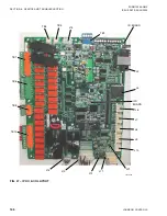
Refer to the unit wiring diagram.
Pressure inputs are
connected to the microboard on plugs J7 and J9. These
analog
inputs represent varying dc signals corresponding
to varying pressures. All voltages are in reference to the
unit case (ground).
System 1 discharge and suction pressures will be
connected to J7 of the microboard. System 2 discharge
and suction pressure transducers will be connected to
J9 of the microboard.
The discharge transducers are optional on all units. If the
discharge transducers are not installed, no connections
are made to the microboard and the discharge pressure
readout on the display would be zero.
The suction pressure transducers are standard on all
YCAL’s. The suction pressure transducers have a range
of 0 psig to 400 psig. The output will be linear from
0.5 VDC to 4.5 VDC over the 400 psig (27.58 barg)
range.
The discharge transducers have a range from 0 psig
to 650 psig. The output will be linear from 0.5 VDC
to 4.5 VDC over the 650 psig (44.82 barg) range.
Following is the formula that can be used to verify the
voltage output of the transducer. All voltage readings
are in reference to ground (unit case).
V = (Pressure in psig x 0.006) + .5
or
V = (Pressure in BARG x 0.09) + .5
Where V = dc voltage output
Pressure = pressure sensed by transducer
The microboard connections for the Discharge
Transducers:
System 1 Discharge Transducer
J7-6 = +5VDC regulated supply to transducer.
J7-11 =VDC input signal to the microboard.
See
the formula above for voltage readings
that correspond to specific discharge
pressures.
J7-7 = +5VDC return
J7-2 = drain (shield connection = 0VDC)
Summary of Contents for YCAL0012EC
Page 12: ...JOHNSON CONTROLS 12 FORM 150 66 NM2 ISSUE DATE 09 25 2020 THIS PAGE INTENTIONALLY LEFT BLANK...
Page 16: ...JOHNSON CONTROLS 16 FORM 150 66 NM2 ISSUE DATE 09 25 2020 THIS PAGE INTENTIONALLY LEFT BLANK...
Page 98: ...JOHNSON CONTROLS 98 FORM 150 66 NM2 ISSUE DATE 09 25 2020 THIS PAGE INTENTIONALLY LEFT BLANK...
Page 142: ...JOHNSON CONTROLS 142 FORM 150 66 NM2 ISSUE DATE 09 25 2020 THIS PAGE INTENTIONALLY LEFT BLANK...
Page 165: ...FORM 150 66 NM2 ISSUE DATE 09 25 2020 165 JOHNSON CONTROLS NOTES...