YORK INTERNATIONAL
7
FORM 155.16-O3
manual operation of the refrigerant level solenoid is only
allowed in MANUAL PUMPS key via the special access
code in the PROGRAM MODE. If the refrigerant level
solenoid is manually energized (open), it is de-energized
(closed) as follows:
• Manually, using the DISPLAY DATA key
• Automatically, if the mode is changed for SERVICE to
LOCAL or REMOTE
Whenever the refrigerant level float switch is open, the
dilution cycle is inhibited or terminated.
Whenever the panel is placed in MANUAL SOLENOID
OPERATION in SERVICE mode through the use of the
MANUAL PUMPS key via the special access code in
PROGRAM mode, both the refrigerant solenoid valve
and the stabilizer refrigerant solenoid valve fall under
manual control. With the exception of the automatic
decrystallization routine, neither pump will respond to
any automatic control while manual control is active. If
the automatic decrystallization routine become active,
the refrigerant stabilizer solenoid valve is reverted from
manual control back to automatic control for as long as
the decrystallization, routine is active. At the end of the
automatic decrystallization, the refrigerant stabilizer so-
lenoid, if previously in MANUAL mode, will once again
fall under manual operation. When automatic solenoid
operation is selected using the same procedure de-
scribed above, manual control of the refrigerant level
solenoid valve is inhibited and only automatic controls
will affect the operation of the valves. Upon exit form
SERVICE mode, if the valves are in MANUAL OPERA-
TION mode, they will automatically switch to automatic
solenoid control operation.
When the unit is running, there are two different fea-
tures designed to prevent crystallization; if unit is
equipped with EPROM version A.02F.00, the STRONG
SOLUTION TEMP CONTROL is used. If the unit is
equipped with EPROM version A.02F.01 or later, this is
replaced by “LOW ENTERING CONDENSER WATER
TEMP LOAD LIMIT”.
When the unit is equipped with EPROM version A.02F.00,
three temperatures are monitored to perform STRONG
SOLUTION TEMP CONTROL as follows:
• Refrigerant Temperature Leaving the Condenser
(RTLC)
• Strong Solution Temperature
• Leaving Chilled Water Temperature (LCWT)
The first two sensor temperatures are displayed via the
REFRIGERANT / SOL’N TEMPS keys using a scrolling
technique. Whenever the RTLC is between 72°F and
117°F (22.2°C and 47.2°C), the strong solution tempera-
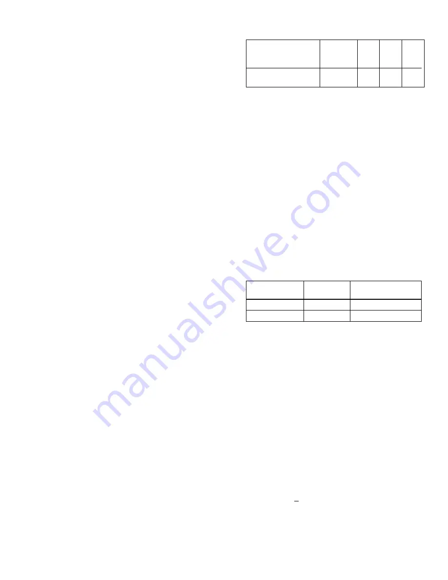
ture shall not exceed the values listed following:
For RTLC values between 72°F and 117°F (22.2°C and
47.2°C), but not listed in the table, the corresponding
maximum strong solution temperature is interpolated. If
the strong solution temperature exceeds the allowable
limit, steam or hot water control valve loading is inhib-
ited and the RTLC/strong solution temperature algorithm
is enabled to slowly pulse the valve closed (based on
the table below) until the strong solution temperature is
less than or equal to the limit. However, if the leaving
chilled water temperature is less than or equal to the
setpoint, the steam or hot water control valve is closed
in accordance with the LCWT automatic temperature
control algorithm. Whenever the RTLC limits loading, the
displayed message is “SYSTEM RUN - STRONG SO-
LUTION TEMP CONTROL”. When the RTLC limits load-
ing, if subsequently the RTLC check determines that the
specified temperature is 1.0°F (.6°C) below the maxi-
mum, the message is replaced with “SYSTEM RUN -
LVG CHILLED WATER CONTROL”, and the automatic
temperature control algorithm is in effect.
If the unit is equipped with EPROM version A.02F.01,
the STRONG SOLUTION TEMP CONTROL is replaced
by LOW ENTERING CONDENSER WATER TEMP
LOAD LIMIT. After a 30 minute bypass at unit start, when-
ever the entering condenser water temperature is < 74°F
(23.2°C), the maximum allowed steam/hot water valve
position is determined by the valve profile. This profile
includes the valve size, flow characteristics and linear-
ity. These parameters are stored in memory and ac-
cessed based on the YORK part number of the value
used on the unit. This part number is entered by a quali-
fied serviced technician using a procedure in the “Ser-
vice” manual, Form 155.16-M3. While the loading is be-
ing limited due to this condition, “SYSTEM RUN - LOW
ECDWT LIMIT IN EFFECT” is displayed. Units equipped
with EPROM version A.02F.02 and later, in addition to
requiring the entering condenser water temperature to
be <74°F (23.2°C), also require the strong solution tem-
perature to be > the LOW ECDWT SOLUTION TEMP
OVERRIDE setpoint to perform this load limit. This
setpoint is entered by a qualified service technician us-
ing a procedure in “Service” manual, Form 155.16-M3.
An upper limit on entering condenser water tempera-
VALVE
PULSE
INTERVAL
TYPE
DURATION
BETWEEN PULSES
BUTTERFLY
1 second
15 seconds
CAGE/GLOBE
2 seconds
60 seconds
Maximum Refrigerant
Temperature Leaving
(°F)
72
97
104
117
the Condenser (RTLC) (°C) 22.2
36.1
40
47.2
Strong Solution
(°F)
170
205
214
231
Temperature
(°C) 76.7
96.1
101.1 110.6
Summary of Contents for MILLENNIUM YIA-HW-14F3
Page 116: ...YORK INTERNATIONAL 115 FORM 155 16 O3 NOTES...
Page 117: ...116 YORK INTERNATIONAL NOTES...


