YORK INTERNATIONAL
99
FORM 155.16-O3
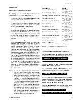
SYSTEM RUN – UNIT HOLDING
is displayed. If the system is not running,
SYSTEM READY TO START – UNIT HOLDING
is displayed. The unit will continue holding until the HOLD,
UNLOAD, or AUTO (returns unit to automatic, leaving
water temp control) key is pressed.
AUTO – Press and release this key to place the unit in
automatic leaving water temperature control. Load and
unload signals are applied to the hot water valve or steam
valve (steam-fed units) automatically as required to con-
trol the leaving water temperature to the desired LEAV-
ING WATER TEMP setpoint.
SYSTEM RUN – AUTO TEMP CONTROL
is displayed. When
the Control Center is in LOCAL, REMOTE, or PRO-
GRAM operating mode, the unit is automatically placed
in AUTO mode.
This key is also used to perform the auto calibration of
the steam or hot water valve position feedback potenti-
ometer. This operation should be performed only by a
qualified service technician. A special access code is
required. The service technician should refer to the cali-
bration procedure in the “Service” manual, Form 155.16-
M3.
OTHER SERVICE KEYS
WARNING RESET – This key is used (in any operat-
ing mode) to turn off the audible alarm that is turned on
by the occurrence of any of the following warning condi-
tions. This key is also used (in SERVICE mode) to clear
the warning message (after the condition that caused
the alarm has reached the Reset threshold). Refer to
description of warning messages in “Display Messages”
section.
WARNING – Low Refrigerant Temperature
WARNING – High Gen Pressure Override
WARNING – High Hot Water Supply Temp
1
WARNING – Ent Cond Water Temp High Limit
WARNING – Faulty Strong Soln Temp Sensor
WARNING – Purge Pump Service Recommended
WARNING – Purge Pump Overloads Open
WARNING – Replace RTC, U16 – Reprogram Setpoints
NOTE: 1. Hot water units only (Micro Board program
jumper JP1 is “OUT”)
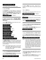
MANUAL PUMP – This key is used to (1) perform a
manual dilution cycle, (2) control the individual system
pumps, (3) enable or disable the automatic operation of
the refrigerant solenoids (4) control the stabilizer refrig-
erant solenoid valve (when in MANUAL control).
IMPORTANT!
Functions (3) and (4) should only be performed by a
qualified service technician. Instructions are in Control
Center “Service” manual, Form 155.16-M3 under “Spe-
cial Setpoints and Programming Procedures”.
To manually control the system pumps or initiate a
manual dilution cycle, proceed as follows:
a. PURGE PUMP – The purge pump can be manu-
ally operated in LOCAL, REMOTE or SERVICE
mode. If it is desired to operate it in LOCAL or
REMOTE mode, place Control Center in the SER-
VICE mode, press and release the DISPLAY
HOLD key, then proceed to Step b. If it is desired
to operate it in SERVICE mode, then proceed to
Step b. The “Display Hold” feature is automatically
engaged when using the PUMP STATUS key in
SERVICE mode. It will remain engaged until the
DISPLAY HOLD key is pressed or 10 minutes have
elapsed, whichever occurs first.
ALL OTHER PUMPS, MANUAL DILUTION CYCLE and
STABILIZER REFRIGERANT SOLENOID VALVE,
place Control Center in SERVICE mode. The “Display
Hold” feature is automatically engaged when using the
PUMP STATUS key in SERVICE mode. It will remain
engaged until the DISPLAY HOLD key is pressed or 10
minutes have elapsed, whichever occurs first.
b. Press and hold the PUMP STATUS key until the
desired function is displayed. Immediately release
the key. The functions will scroll in this order:
PURGE PUMP – OFF
1
REFRIGERANT PUMP – OFF
2, 6
SOLUTION PUMP – OFF
2, 4
CHILLED WATER PUMP – OFF
2
CONDENSER WATER PUMP – OFF
2
ABSORBER PUMP – OFF
2, 4
GENERATOR PUMP – OFF
2, 4
MANUAL DILUTION CYCLE – OFF
3
STABILIZER REF SOLENOID VALVE – CLOSED
5
Summary of Contents for MILLENNIUM YIA-HW-14F3
Page 116: ...YORK INTERNATIONAL 115 FORM 155 16 O3 NOTES...
Page 117: ...116 YORK INTERNATIONAL NOTES...

