background image

1133391-YIM-A-1014

48

Johnson Controls Unitary Products

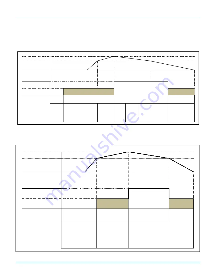
 Indoor blower operation is initiated upon a call for first stage 
cooling, second stage cooling or dehumidification. 

Anytime there is a call for a second stage of cooling, the unit will 
not operate in the reheat mode, even if there is still a call for 
dehumidification at terminal RAT.

 The unit will not operate in the reheat mode if there is any call 
for heating. 

All safety devices function as previously described.

Figure 29: Dehumidification With No Y1 Call For Cooling

Figure 30: Dehumidification With A Y1 Call For Cooling

Y2

Temperature High calling 
for cooling

1

Y

1

Y

Temperature 

ƐĂƟƐĮĞĚ

Compressor On, No Reheat

Compressor On, Reheat

Compressor 

No Reheat


ĞŚƵŵŝĚŝĮĐĂƟŽŶ

     w/Reheat

Y1 Call for 

Cooling is 

ƐĂƟƐĮĞĚ

Y1 Call for Cooling , 

ĞŚƵŵŝĚŝƐƚĂƚ

 Calling

Y2 Call for 

Cooling

De-

ŚƵŵŝĚŝƐƚĂƚ


calling or not 

calling

Y2 Call for 

Cooling is 

ƐĂƟƐĮĞĚ

Y1 is Calling for 

Cooling,                

ĞŚƵŵŝĚŝƐƚĂƚ


is


not


calling

Y1

 is 

Calling


for


Cooling,


De-

ŚƵŵŝĚŝƐƚĂƚ

 is calling


ĞŚƵŵŝĚŝĮĐĂƟŽŶ

 w/Reheat

De-

ŚƵŵŝĚŝƐƚĂƚ

 calling, 

,ƵŵŝĚŝƚLJ


ƌĞĚƵĐƟŽŶ


with no Sensible Cooling

No Reheat

Operational Sequence Of the 3-5 Ton Hot Gas Reheat Unit

Y2 Setpoint is 2 

ĚĞŐƌĞĞƐ

 above                   

Y1 Setpoint

Y2

Temperature High calling 

for cooling

Y1

Y1

Temperature sa

Ɵ

s

Į

ed

Compressor On, No Reheat

Compressor On, Reheat

Compressor O

ī

Y2 Setpoint is 2 

degrees above Y1 

Operational Sequence Of the 3-5 Ton Hot Gas Reheat Unit

Y1 Call for Cooling is Sa

Ɵ

s

Į

ed

Y1 is Calling for Cooling,      

De-humidistat is calling

Y2 is Calling for Cooling,              

De-humidistat is calling              

or not calling

Y1 is Calling           

for Cooling,           

De-humidistat is 

calling

No Reheat

 Dehumidi

Į

ca

Ɵ

on w/Reheat

No Reheat

 Dehumidi

Į

ca

Ɵ

on 

w/Reheat

Summary of Contents for ZR Series

Page 1: ...tion 40 17 ZR037 061 Bottom Duct Application 41 18 RPM Selection 42 19 Indoor Blower Specifications 42 20 Power Exhaust Specifications 42 21 Motor Sheave Datum Diameters 44 22 Additional Static Resist...

Page 2: ...est edition Wear safety glasses and work gloves Use quenching cloth and have a fire extinguisher available during brazing operations Improper installation may create a condition where the operation of...

Page 3: ...combustible flooring or in the U S on wood flooring or Class A Class B or Class C roof covering materials 4 For use with natural gas convertible to LP with kit This product must be installed in strict...

Page 4: ...is not listed above ZZ will be assigned and configuration options will be located in digits 15 18 Two Stage Natural Gas Heat Options A05 49 MBH Output Aluminized Steel Single Stage 037 049 A07 65 MBH...

Page 5: ...Bracket 2 Turn each bracket toward the ground and the protective plywood covering will drop to the ground 3 Remove the condenser coil external protective covering prior to operation 4 Remove the tool...

Page 6: ...n to 0 F when this product is applied in a comfort cooling application for people An economizer is typically included in this type of application When applying this product for process cooling applica...

Page 7: ...g until the unit is near the place of installation Rig the unit by attaching chain or cable slings to the lifting holes provided in the base rails Spreader bars whose length exceeds the largest dimens...

Page 8: ...ght lbs Center of Gravity 4 Point Load Location lbs 6 Point Load Location lbs Shipping Operating X Y A B C D A B C D E F 037 3 ZR 887 867 40 3 25 5 205 170 223 269 141 124 110 144 163 185 049 4 ZR 900...

Page 9: ...Johnson Controls Unitary Products 9 Figure 8 ZR037 Physical Dimensions 25 31 59 00 15 51 29 75 59 LEFT 11 3 8 21 3 16 89 27 5 16 4 3 16 FRONT See detail A for gas inlet A See detail B for drain locati...

Page 10: ...Controls Unitary Products Figure 9 ZR049 061 Physical Dimensions 24 47 TYP 2 PL 15 38 15 38 59 00 15 25 29 69 59 LEFT 11 3 8 21 3 16 89 27 5 16 4 3 16 FRONT See detail A for gas inlet A See detail B...

Page 11: ...3 16 15 3 16 6 3 16 42 CABINET 3 126 2 000 3 184 4 727 7 705 14 594 Gas Pipe Inlet Gas Exhaust Vent 5 3 8 3 4 FPT Table 5 ZR037 061 Unit Clearances Direction Distance in Direction Distance in Top1 1 U...

Page 12: ...nit Bottom Duct Openings Bottom condensate drain Bottom gas supply entry FRONT RETURN AIR SUPPLY AIR RIGHT LEFT 20 1 8 19 1 8 17 1 8 6 13 16 6 13 16 32 11 16 14 1 2 16 3 8 18 1 16 25 9 16 12 5 16 27 1...

Page 13: ...Cover Power Entry 2 1 2 Control Entry 7 8 Power Entry 2 1 2 Convenience Outlet Cover Convenience Outlet Power Entry 7 8 FRONT Dot Plugs 5 5 32 31 11 16 2 31 32 18 1 4 Return Air Supply Air A B C D Ta...

Page 14: ...ary Products Figure 13 ZR037 061 Unit Left Duct Opening Figure 14 ZR037 061 Roof Curb 4 5 16 30 3 8 8 or 14 50 1 2 30 20 20 80 5 8 6 2 TYP INSULATED DECK UNDER COMPRESSOR SECTION INSULATED DECK UNDER...

Page 15: ...bottom duct application no duct cover changes are necessary For side duct application remove the side duct covers and install over the bottom duct openings The panels removed from the side duct conne...

Page 16: ...ing must conform to local codes Use a sealing compound on male pipe threads Install condensate drain line from the 3 4 inch NPT female connection on the unit to an open drain Figure 20 Condensate Drai...

Page 17: ...cement wire must be of the type shown on the wiring diagram and the same minimum gauge as the replaced wire A disconnect must be utilized for these units Factory installed disconnects are available If...

Page 18: ...the unit nameplate Refer to Electrical Data Table 8 to size power wiring fuses and disconnect switch Power wiring is brought into the unit through the side of the unit or the basepan inside the curb F...

Page 19: ...Wire Sizes Wire Size Maximum Length1 1 From the unit to the thermostat and back to the unit 18 AWG 150 Feet OCC C RC G Y2 Y1 W2 W1 X R THERMOSTAT TERMINALS CONTROL TERMINAL BLOCK TERMINALS ON A LIMITE...

Page 20: ...2 41 6 58 5 65 4 60 70 230 11 9 88 0 18 5 2 1 5 2 5 5 0 0 None 24 3 29 8 35 40 E06 6 0 1 14 4 24 5 31 4 35 40 E08 9 0 1 21 7 33 6 40 4 35 45 E15 15 0 2 36 1 51 6 58 5 60 60 E20 20 0 2 48 1 66 6 73 5...

Page 21: ...8 1 18 9 30 1 37 0 35 40 E15 11 3 2 31 4 45 7 52 6 50 60 E20 15 0 2 41 6 58 5 65 4 60 70 230 11 9 88 0 18 5 2 1 5 2 5 5 0 0 None 24 3 29 8 35 40 E06 6 0 1 14 4 24 5 31 4 35 40 E08 9 0 1 21 7 33 6 40...

Page 22: ...1 18 9 42 6 49 5 45 50 E15 11 3 2 31 4 58 2 65 1 60 70 E20 15 0 2 41 6 71 0 77 9 80 80 230 11 9 88 0 18 5 2 1 5 2 5 5 10 0 None 34 3 39 8 45 50 E06 6 0 1 14 4 37 0 43 9 45 50 E08 9 0 1 21 7 46 1 52 9...

Page 23: ...1 18 9 42 6 49 5 45 50 E15 11 3 2 31 4 58 2 65 1 60 70 E20 15 0 2 41 6 71 0 77 9 80 80 230 11 9 88 0 18 5 2 1 5 2 5 5 10 0 None 34 3 39 8 45 50 E06 6 0 1 14 4 37 0 43 9 45 50 E08 9 0 1 21 7 46 1 52 9...

Page 24: ...ges 1 1 1 1 1 1 1 1 1 Temperature Rise Range F 20 50 F 25 65 F 35 80 F 20 50 F 25 65 F 35 80 F 25 65 F 35 80 F 45 75 F Gas Limit Setting F 200 F 235 F 290 F 200 F 235 F 290 F 235 F 290 F 240 F Gas pip...

Page 25: ...12 x 9 12 x 9 12 x 9 Type Centrifugal Centrifugal Centrifugal Motor Sheave 1VP34 1VL44 1VP34 1VL44 1VP34 1VL44 Blower Sheave AK61 AK59 AK61 AK59 AK61 AK59 Belt A47 A47 A47 A47 A47 A47 Motor HP each 1...

Page 26: ...2 22 22 22 22 Temperature Rise Range F 20 50 F 25 65 F 35 80 F 20 50 F 25 65 F 35 80 F 25 65 F 35 80 F 45 75 F Gas Limit Setting F 200 F 235 F 290 F 200 F 235 F 290 F 235 F 290 F 240 F Gas piping conn...

Page 27: ...2 x 9 12 x 9 12 x 9 Type Centrifugal Centrifugal Centrifugal Motor Sheave 1VP34 1VL44 1VP34 1VL44 1VP34 1VL44 Blower Sheave AK61 AK59 AK61 AK59 AK61 AK59 Belt A47 A47 A47 A47 A47 A47 Motor HP each 1 1...

Page 28: ...with the local gas utility Figure 23 Side Entry Gas Piping NOTE Routing of gas piping must not interfere with the flue or heat compartment access Figure 24 Bottom Entry Gas Piping NOTE Maximum capacit...

Page 29: ...mbers 1NP0454 or 1NP0455 All LP gas equipment must conform to the safety standards of the National Fire Protection Association Table 12 Gas Heat Minimum Supply Air Size Tons Model Heat Size Supply Air...

Page 30: ...at least once a year For specific troubleshooting and maintenance procedures please refer to the smoke detector s installation instructions which accompanies the unit Motorized Outdoor Damper The Moto...

Page 31: ...ly fan system both set points should be set to the same value Free Cooling Four types of free cooling options are available dry bulb changeover single enthalpy dual enthalpy changeover and Auto Dry Bu...

Page 32: ...one stage of cooling If the economizer output goes to minimum position and the SAT is less than Economizer Setpoint 1 F the control starts a 12 minute timer to de energize a compressor output If at an...

Page 33: ...r actuator position feedback Connects through circuit trace to 24V IN pin HOT C COM Mixed Air Temperature sensor input from 10K 77 F Type III negative temperature coefficient thermistor MAT parameter...

Page 34: ...FType selection is Modulating Damper Used to ramp the power exhaust fan VFD position the discharge damper actuator COM 24 VAC common 0 10 VDC negative for the power exhaust variable frequency drive di...

Page 35: ...e Indoor Air Quality sensor IAQRange parameter sets the CO2 parts per million measured by the indoor air quality sensor when it outputs 10 VDC IAQ parameter reports input status 0 5000ppm Used for dem...

Page 36: ...n proper rotation Blower Rotation Check for proper supply air blower rotation If the blower is rotating backwards the line voltage at the unit point of power connection is misphased See PHASING R 24V...

Page 37: ...ensity of the air However since the air at high altitude is less dense less static pressure will be generated and less power will be required than a similar application at sea level Air density correc...

Page 38: ...iven is at an elevation of 5 000 ft The first step is to convert this static pressure to equivalent sea level conditions Sea level static pressure 1 5 832 1 80 Enter the blower table at 6000 sCFM and...

Page 39: ...or and drive 5 turns open will achieve 1230 RPM Example Supply Air Blower Performance Air Flow CFM Available External Static Pressure IWG 0 2 0 4 0 6 0 8 1 0 1 2 1 4 1 6 1 8 2 0 RPM BHP RPM BHP RPM BH...

Page 40: ...27 0 5 719 0 6 801 0 6 876 0 7 943 0 8 1005 0 9 1063 1 0 1117 1 1 1169 1 2 1400 537 0 5 639 0 5 731 0 6 813 0 7 888 0 7 955 0 8 1017 0 9 1075 1 0 1129 1 1 1181 1 2 1500 549 0 5 650 0 6 742 0 6 824 0 7...

Page 41: ...0 8 942 0 8 994 0 9 1046 1 0 1100 1 2 1157 1 3 1400 617 0 5 705 0 6 781 0 6 847 0 7 907 0 8 962 0 9 1014 1 0 1066 1 1 1119 1 2 1177 1 3 1500 637 0 6 724 0 6 800 0 7 867 0 8 927 0 8 981 0 9 1034 1 0 1...

Page 42: ...ection Size Tons Model Airflow Option HP Max BHP Motor Sheave Blower Sheave 6 Turns Open 5 Turns Open 4 Turns Open 3 Turns Open 2 Turns Open 1 Turn Open Fully Closed 037 3 0 ZR Std 1 5 1 5 1VP34 AK61...

Page 43: ...ble motor sheave is open 5 Select the correct blower performance table for the unit from Tables and 17 Tables are presented for side and downflow configuration 6 Determine the unit Measured CFM from t...

Page 44: ...allation errors leaks or undesirable systems effects that can result in loss of airflow Even small changes in blower speed can result in substantial changes in static pressure and BHP BHP and AMP draw...

Page 45: ...02 0 03 0 01 0 01 0 01 0 02 0 02 0 02 1200 0 04 0 00 0 04 0 01 0 01 0 01 0 02 0 02 0 02 1300 0 03 0 01 0 05 0 01 0 01 0 01 0 03 0 03 0 03 1400 0 03 0 03 0 07 0 02 0 02 0 02 0 03 0 03 0 03 1500 0 03 0...

Page 46: ...he AUTO position and drives the economizer dampers from fully closed to their minimum position If the enthalpy of the outdoor air is below the setpoint of the enthalpy controller previously determined...

Page 47: ...B will not lockout the compressor due to a freezestat trip However a freezestat trip will de energize the compressor If the call for cooling is still present at the end of the ASCD and the freezestat...

Page 48: ...On Reheat Compressor K No Reheat w Reheat Y1 Call for Cooling is Y1 Call for Cooling Calling Y2 Call for Cooling De calling or not calling Y2 Call for Cooling is Y1 is Calling for Cooling is notcalli...

Page 49: ...il Condensing coil 1 and the Reheat coil are active and the condensing coil 2 is inactive Refrigerant Recovery Valve 2 Sol 2 is opened allowing refrigerant to return to the active system Refrigerant R...

Page 50: ...ed by inadequate supply air flow occurs thus shutting down the heater and energizing the blower Reset Remove the call for heating by lowering the thermostat setting lower than the conditioned space te...

Page 51: ...unit fails after three ignition attempts the furnace is locked out for one hour The furnace is monitored during this one hour period for unsafe conditions Recycle Operation When a flame is lost after...

Page 52: ...the pressure switch opens for 2 seconds the GV will be de energized the ignition cycle is aborted and the ICB flashes the appropriate code See Table 29 Ignition Control Flash Codes The draft motor is...

Page 53: ...Check for correct manifold gas pressures See CHECKING GAS INPUT 3 Check the supply gas pressure It must be within the limits shown on the rating nameplate Supply pressure should be checked with all g...

Page 54: ...bic foot test dial 5 Using the number of seconds it takes for one revolution of the dial calculate the cubic feet of gas consumed per hour See example below 6 If necessary adjust the low pressure regu...

Page 55: ...unit on first stage 9 Once pressure has been checked replace the plastic cap covering the HI and LO pressure adjustment screws NOTE When using natural gas the manifold pressure for second stage 100 i...

Page 56: ...nstallation and operation guides are located on www upgnet com under Product Center Equipment Catalog Commercial Products Zoning Systems and Controls 1 Local LCD on Unit Control Board 2 Mobile Access...

Page 57: ...the cursor is on the top Status line hit the ENTER button This action steps the LCD display into the status mode Hit ENTER to view the status menu Press Enter Step 2 Scroll down to DVent Mode This is...

Page 58: ...aged ENTER CANCEL JOY C PWR 7 7 77 Clg Engaged LeadLag Engaged Press Enter Joy Stick Down 2 Step 6 By toggling down 4 times the screen reaches the ClgOcc SP screen or Cooling Occupied Set Point ENTER...

Page 59: ...microprocessor connects through circuit trace to the SD 24 terminal SD 24 24 VAC hot out for factory accessory smoke detector condensate overflow and or user shutdown relay switching in series Connec...

Page 60: ...Lit indicates 24 VAC is present at C and 24V terminals FAULT Red hard lockout networking error and firmware error indicator 1 2 second on off flashing indicates one or more alarm is currently active 1...

Page 61: ...tor Input required for operation of 2 compressor units not active for 1 compressor units 3 625 VDC reading EC2 to EC2 with open circuit Used in suction line temperature safety Pinned connections on ri...

Page 62: ...reheat components Effective only for reheat units output with reheat operation FAN 24 VAC hot output for indoor blower contactor coil indoor blower VFD enable relay coil Output with heat cool operati...

Page 63: ...nter of the board Positive of the 15 VDC reading to C circuit for powering an optional netstat and or Multi Touch gateway C Common for SA BUS power and communication circuits Also incorporated in the...

Page 64: ...BUS BACnet MSTP communication circuit Earth ground reference of the cable to prevent interference on the FC bus BACnet MSTP communication circuit Item Selector in red housing at left on top edge of t...

Page 65: ...incline manometer digital manometer or Magnehelic gauge teed into the pressure switch sensing line verify that the negative pressure exceeds the setting listed on the induced draft pressure switch la...

Page 66: ...16 6 7 95 171 71 383 102 14 7 3 400 Cfm Ton 75 63 75 138 62 288 82 21 6 3 85 141 62 321 90 20 6 7 95 144 61 372 98 18 7 2 Table 31 ZR049 Charging Table Air Flow Indoor Db Wb Outdoor DB Suction Pressu...

Page 67: ...102 22 11 4 300 Cfm Ton 80 72 75 151 72 278 84 20 9 6 85 156 71 309 93 19 10 3 95 162 69 354 102 18 11 5 300 Cfm Ton 75 63 75 131 58 279 87 24 9 8 85 135 58 300 92 22 10 1 95 140 56 347 100 21 11 2 4...

Page 68: ...up This confidence is supported by the 30 day dealer protection coverage portion of our standard warranty policy which states that Johnson Controls UPG will cover parts and labor on new equipment star...

Page 69: ...full open position and the frequency drive is operating at 60 HZ Do not proceed with the equipment start up without the design CFM information Design Supply Air CFM __________________________ Design...

Page 70: ...omplete Air Moving Inspection Completed See Notes Alignment of drive components Belt tension adjusted properly Blower pulleys tight on shaft bearing set screws tight wheel tight to shaft Pressure swit...

Page 71: ...to increase of decrease the airflow to meet the design conditions If the motor pulley size was changed measure the outside diameters of the motor and blower pulleys and record those diameters here Bl...

Page 72: ...Return Air Temperature ________________ F db ________________ F wb ________________ RH Mixed Air Temperature ________________ F db ________________ F wb ________________ RH Supply Air Temperature ____...

Page 73: ...____________________________________________________________________ ________________________________________________________________________________________________________ __________________________...

Reviews: