YOKOGAWA ZO21DW User Manual Download Page 21

<4.  WIRING>

4-2

IM 11M03A02-00E 

4.1.2 

Wiring Procedure

Wiring should be performed according to the following procedure:
1.  Be sure to connect the shield line to FG terminal of the converter.
2.  The outer sheath of the signal line should be stripped to a length of 50 mm or less. The most 

outer sheath of the power cable should be stripped to a length of 20 mm or less.

3.  Signals may be affected by noise if signal lines, power cable and heater cable are located in 

the same conduit. When using conduit, signal lines should be installed in a separate conduit 

than power and heater cables.

4.  Install metal blind plug(s) in unused cable connection gland(s) of the converter.
5.  Metal conduit should be grounded.

1

FG

2

AO1

(+)

3

AO1

(-)

4

AO2

(+)

5

AO2

(-)

6

CJ

(+)

7

CJ

(-)

8

TC

(+)

9

TC

(-)

10

CELL

(+)

11

CELL

(-)

12

FG

13

DI-1

14

DI-2

15

DI-C

16

AI

(+)

17

AI

(-)

18

AC-

ZERO

19

AC-

SPAN

20

AC-

COM

21

FG

22

FG

CELL

(+)

CELL

(-)

TC

(+)

TC

(-)

CJ

(+)

CJ

(-)

23

DO-1

24

DO-1

25

DO-2

26

DO-2

27

DO-3

28

DO-3

29

DO-4

30

DO-4

31

HTR

32

HTR

33

L

34

N

35

G

36

FG

HTR HTR

100-240V AC

50/60 Hz

F4.1E.ai

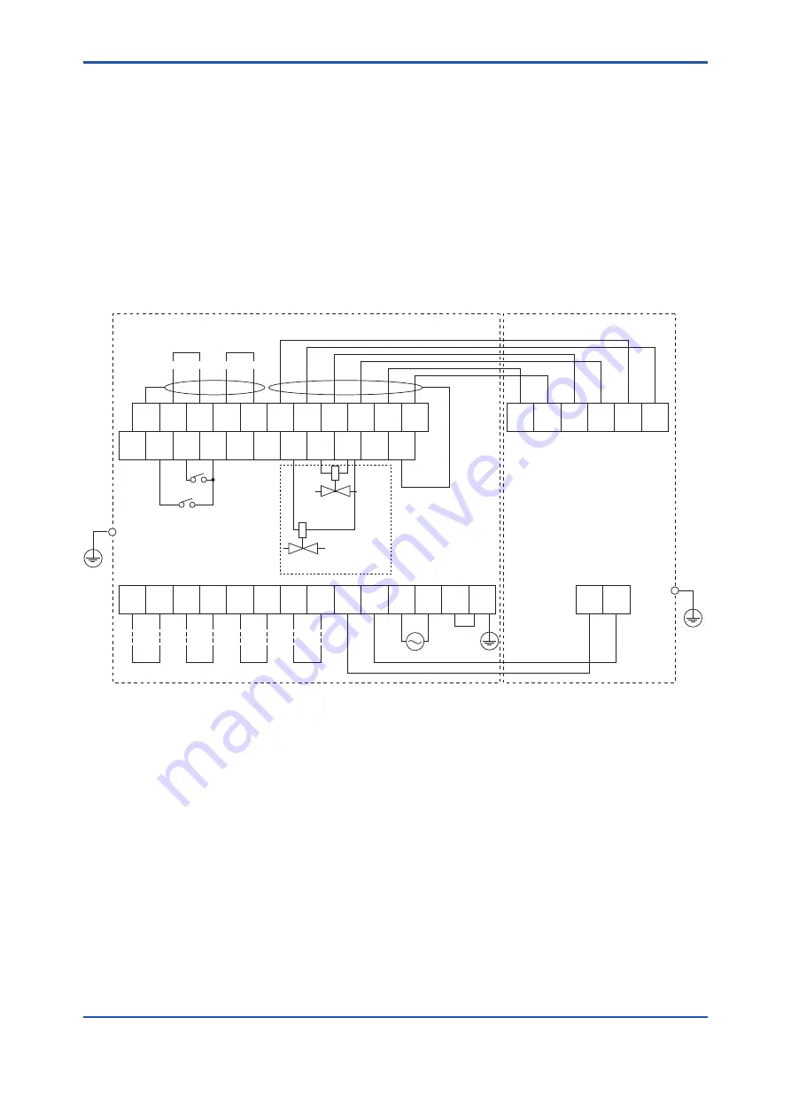
Model ZR402G Separate type Zirconia Oxygen Analyzer/ 

Converter

Zirconia Oxygen Analyzer, 

Model ZO21DW Detector 

Analog 

output 2

Analog 

output 1

4-20 mA DC

4-20 mA DC

Digital output

Contact 

input 2

Contact input 1

Contact 

output 1

Contact 

output 2

Contact 

output 3

Contact 

output 4

Solenoid valve for span gas  

for automatic calibration

Solenoid valve for zero gas 

for automatic calibration

Flow setting unit

*1

*1

The protective grounding for the converter should be connected to either the protective ground terminal in the equipment or 

the ground terminal on the case.

Grounding standard: JIS D type (Class 3 grounding), ground resistance: 100 

 or less.

*1

Figure 4.1 

Wiring connection to the converter (ZR402G)

Summary of Contents for ZO21DW

Page 1: ...User s Manual In Situ Type Zirconia Oxygen Analyzer Model ZO21DW Detector IM 11M03A02 00E IM 11M03A02 00E 3rd Edition...

Page 2: ...the measured gas and reference gas pressures can be kept at about the same level making high accuracy measurements possible This instruction manual describes all the handling and operations of the Mod...

Page 3: ...when connecting power supply Some process gas is dangerous to people When removing this equipment from the process line for maintenance or other reasons protect yourself from potential poisoning by us...

Page 4: ...dy of injury electric shock or fatalities The manual describes what special care the operator must take to avoid such risks CAUTION This symbol indicates that the operator must refer to the instructio...

Page 5: ...ty period Failure of components which are out of scope of warranty stated in instruction manual Failure caused by usage of software hardware or auxiliary equipment which Yokogawa Electric did not supp...

Page 6: ...red for Piping in System 1 3 2 3 1 2 Connection to the Calibration Gas Inlet 3 2 3 1 3 Piping for the Reference Gas Inlet 3 3 3 2 Piping for System 2 3 4 3 2 1 Piping Parts for System 2 3 4 3 2 2 Pipi...

Page 7: ...1 4 Calibration 6 1 6 2 Stationary Operation 6 2 6 2 1 Checking Operating Conditions 6 2 6 2 2 Stopping and Restarting Operations 6 2 7 INSPECTION AND MAINTENANCE 7 1 7 1 Inspection and Maintenance o...

Page 8: ...e instrument air Reference gas is discharged into the furnace Material in Contact with Gas SUS316 Zirconia SUS304 JIS or ASTM grade 304 flange Installation Flange mounting Probe mounting angle Between...

Page 9: ...m 150 1 5 m 200 2 0 m 300 3 0 m Flange joint connection J JIS 10K 100 FF A ANSI Class 150 4 RF E DIN PN10 DN100 4 Style code A Style A Options CV With check valve SV With stop valve G Cable glands 2 p...

Page 10: ...210 175 8 19 18 Approx 6 5 ZO21DW L 100 J A 1000 Approx 10 ZO21DW L 150 J A 1500 Approx 13 ZO21DW L 200 J A 2000 Approx 17 ZO21DW L 300 J A 3000 Approx 20 ZO21DW L 040 A A 400 ANSI CLASS 150 4 RF or...

Page 11: ...Blank Page...

Page 12: ...as inlet should face downwards When using the detector with pressure compensation ensure that the flange gasket does not block the reference gas outlet on the detector flange If the flange gasket bloc...

Page 13: ...rtion hole 2 3 Detector Installation CAUTION The cell sensor at the tip of the detector is made of ceramic zirconia Do not drop the detector as inpact will damage it The gasket should be used on the f...

Page 14: ...System 2 Instrument air is used as the reference gas This instrument air is also used as the span gas in calibration The zero gas in calibration is supplied from the zero gas cylinder System 3 Basical...

Page 15: ...or G7016XH Nipple R1 4 or 1 4 NPT On the open market Tube connecting joint R1 4 or 1 4 NPT 6 4 mm soft tube On the open market At the reference gas inlet Air set Recommended by YOKOGAWA K9473XH K9473X...

Page 16: ...air source fresh air and the flow setting unit and between the flow setting unit and the detector Insert the air set next to the flow setting unit in the piping between the air source and the flow set...

Page 17: ...3 requires piping as follows Mount the check valve or stop valve through a nipple to the reference gas inlet of the detector CAUTION The stop valve should be connected directly to the detector If any...

Page 18: ...and the ZA8F flow setting unit and between the ZA8F flow setting unit and the ZO21DW detector The cylinder should be placed in a calibration gas unit case or the like to avoid any direct sunlight or r...

Page 19: ...in front of the reference gas outlet and after turning on instrument air flow start furnace operation As furnace internal pressure rises confirm that instrument air continues to flow and adjust the v...

Page 20: ...of converter Name Need for shields Cable type Number of wires CELL CELL HTR TC HTR TC CJ CJ Converter signal CVVS 6 HEATER Converter heater CVV 2 L N Power supply CVV 2 or 3 AO 1 AO 1 AO 2 AO 2 Analo...

Page 21: ...11 CELL 12 FG 13 DI 1 14 DI 2 15 DI C 16 AI 17 AI 18 AC ZERO 19 AC SPAN 20 AC COM 21 FG 22 FG CELL CELL TC TC CJ CJ 23 DO 1 24 DO 1 25 DO 2 26 DO 2 27 DO 3 28 DO 3 29 DO 4 30 DO 4 31 HTR 32 HTR 33 L 3...

Page 22: ...etector ZR402G Converter F4 2E ai Figure 4 2 Wiring for detector output 4 2 1 Connection to the Detector To connect cables to the detector proceed as follows 1 Mount conduits of the specified thread s...

Page 23: ...F4 3E ai Figure 4 3 Wiring for power to the detector heater 4 3 1 Connection to Detector When connecting the cable to the detector proceed as follows 1 Mount cable glands or conduits of the specified...

Page 24: ...screw threads is M4 Each cable should be terminated corresponding crimp on terminals 4 4 2 Grounding Wiring The ground wiring of the detector should be connected to the ground terminal of the detector...

Page 25: ...Blank Page...

Page 26: ...r cell U shaped pipe F5 1E ai Bolt Spring washer Filter retainer Calibration gas tube Contact Stop valve Vent pipe for reference air Terminal box Waterproof structure Probe Flange Insert this part int...

Page 27: ...Blank Page...

Page 28: ...x 150 kPa when a check valve is used maximum pressure rating is 300 kPa is obtained Turn the reference gas flow setting valve in the flow setting unit to obtain a flow of 800 to 1000 ml min Turning th...

Page 29: ...ssure 1 to 2 week 6 2 2 Stopping and Restarting Operations Operation stoppage Before stopping operations it is important for you not to make the detector sensor inoperable If you stop the operation of...

Page 30: ...ubject the probe to shock or cool it rapidly The sensor is made of ceramic zirconia If the detector is dropped or bumped into something the sensor may be damaged and no longer work 3 Do not reuse a me...

Page 31: ...ed spring washers that tighten the sensor assembly and the pipe support as well as the U shaped pipe 3 Use a rod 2 to 2 5 mm in diameter to clean the calibration gas tube inside the probe In doing thi...

Page 32: ...n the groove The contact s resistance should be minimized Use sensor assemblies manufactured in or after Sept 2000 the serial number on the side of the sensor assembly should be 0J000 or later for exa...

Page 33: ...the U shaped pipe to its support with filter then fully insert the U shaped pipe and its support into the probe 4 Coat the threads of the four bolts with antiseize grease and then screw them in along...

Page 34: ...rt U shaped pipe Filter Sensor Metal O ring Contact Probe F7 3E ai Figure 7 3 Exploded View of Sensor Assembly CAUTION Optional Inconel bolts have a high coefficient of expansion If excess torque is a...

Page 35: ...fix the dusts on itself Consequently the dusts can make the sensor performance very lower If a large amount of water is condensed the sensor can be broken and never re useful To prevent the above nonc...

Page 36: ...O21DW L J E SV G7013XH 1 Stop Valve for ZO21DW L A SV E7042VR 1 Check Valve for ZO21DW L J E CV E7042VV 1 Check Valve for ZO21DW L A CV 11 G7067XA 1 Nipple for ZO21DW L J E SV G7248XA 1 Nipple for ZO2...

Page 37: ......

Page 38: ...n Analyzer Model ZO21DW Detector Manual No IM 11M03A02 00E Aug 2018 3rd Edition Modified specification of flange material p 1 1 1 2 Revised tables p 3 2 3 5 Revised CMPL 11M06B02 01E to 7th edition Au...

Page 39: ...Blank Page...

Reviews: