


10
IM 04L55B01-02EN
Basic Operation
The basic operation of the GM is explained briefly here. For
details, see the user’s manuals.
Names of the GM10 Parts
START/STOP key
USER key
SD card slot
SD card
USB port
Ethernet port
RS-422/485
Serial port
(/C3 option)
Status display area
7 segment LED×2
7 segment LED:
Displays the operation mode, system No., self-check
operation, key lock, operation error, process running, and
module installation information.
Status display area:
Item
LED color
Description
RDY
Green
System normal indication
REC
Green
Recording status
SD
Orange
SD card access status
FAIL
Red
System error indication
MATH
Green
Computation status
SER
Orange
Serial communication status
BT
Orange
Bluetooth communication status
ALM
Red
Alarm status
START key: Starts recording and computation
STOP key: Stops recording and computation, clears errors
USER keys (USER1/USER2): Executes specified actions
(event action function)
Setting a SD Card
Open the SD card slot cover on the GM10 front panel, and
insert an SD card (see the names of the parts).
Note
On models with the advanced security function (/AS option),
an SD memory card must be installed.
Configuring the GM via Ethernet
Communication
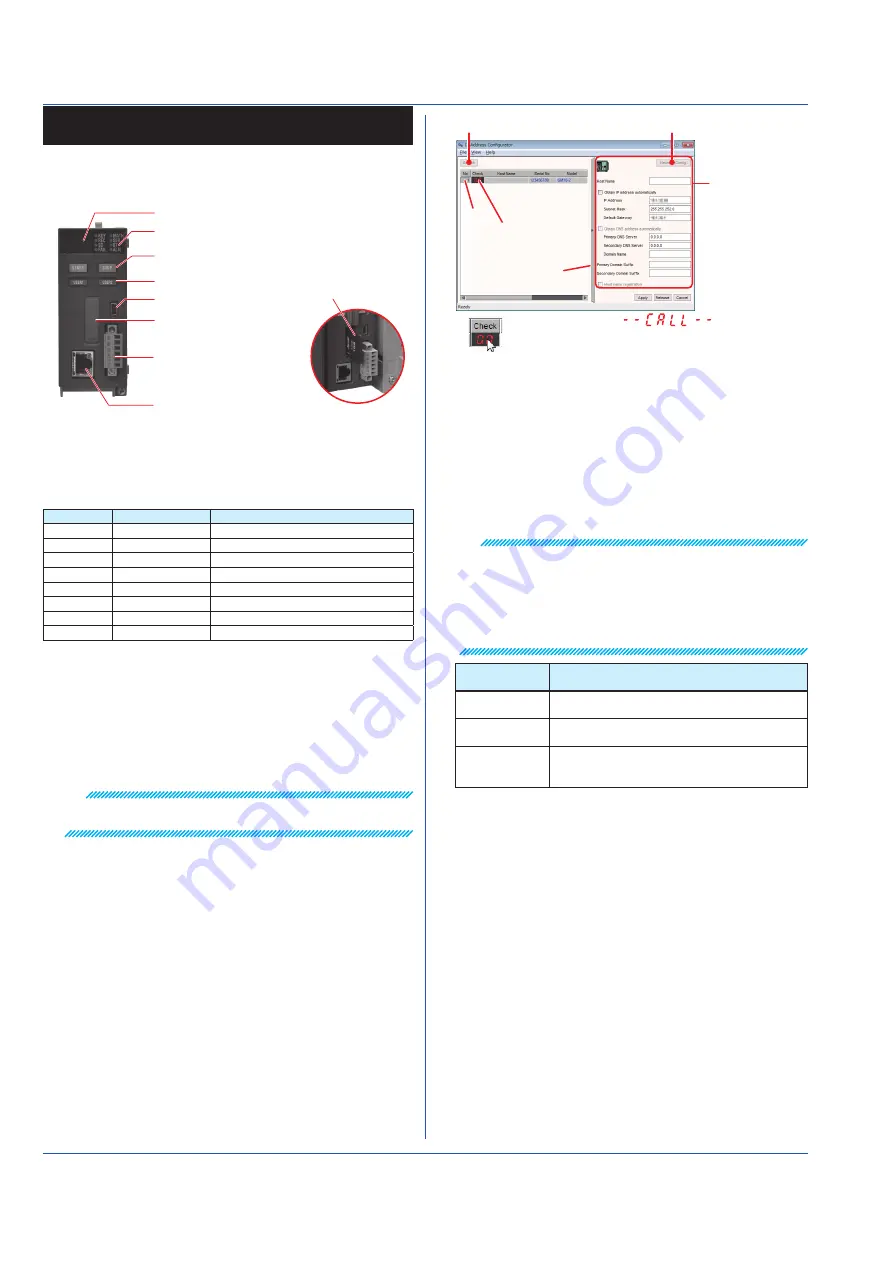
Setting the GM10’s IP address with the IP Address
Configurator
1. Start the IP Address Configurator, and click
Search
. A list
of GM10s in the segment appears.
Search button
Network Config. button
Address setting
screen
[No.]
See below.
Set the IP address,
subnet mask, default
gateway, and so on.
Clicking here will display
on the 7 segment LED of the GM10. This is
convenient to check the corresponding device.
Expand/reduce
button
2. Click a
No.
.
The corresponding GM10 is enabled.
3. Click
Network Config.
, and set the items on the address
setting screen.
For details on the settings, see the IP Address Configurator
User’s Manual.
Setting the Measurement Mode
Set the measurement mode to Normal, High speed, or Dual
interval. The factory default setting is Normal.
Note
When you change the measurement mode, the following data
is initialized.
• All internal data
• All setting parameters except the IP address and other
communication settings (including security settings)
• System configuration data
Measument
mode
Description
Normal
A mode in which the shortest measurement
interval is 100 ms
High speed
A mode in which the shortest measurement
interval is 1 ms
Dual interval
A mode in which measurement is possible by
setting different scan intervals on the two scan
groups.
1. Start the Web browser (IE11 or later).
2. In the Address box, enter “http://” followed by the GM10 IP
address. The Web application starts.
3. On the content selection tree, click the Calib tab.
4. On the content selection tree, click Measurement mode.
5. Select a measurement mode, and click Update
Configuration in the lower right of the screen.
Reconfiguring (Module identification)
Reconfiguration is used to identify the connected I/O modules
to align the system environment to the actual module
configuration.
Reconfiguration is necessary in the following situations.
When the system is used for the first time, when modules
are changed (changed to different types of modules),
when modules are added or removed, or when the system
configuration is changed (connecting a GX90EX)
Do not carry out the following operations while a
reconfiguration is in progress.
Turn the power on or off, remove or insert a module
1. Start the Web browser (IE8 or later).