10-6
IM 253710-01E
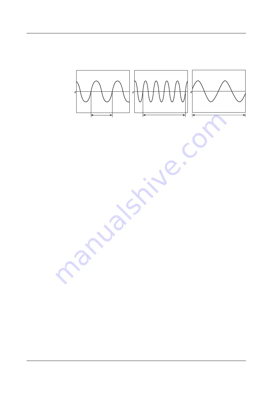
Zero crossing setting
The measurement/computation period is set to the period between the first and last
points on the screen at which the waveform crosses the zero level (zero crossing) with
a positive slope. When there is only one or no positive slope on the screen, the
measurement/computation period is set to the entire width of the screen.
Measurement/computation
period
Measurement/computation
period
Measurement/computation
period (the entire screen)
Selecting the synchronization source
For each element, you can set which input signal to use to synchronize to the zero
crossing point. Select the synchronization source from the following choices.
• CH1 to CH8
The synchronization source is set to the voltage or current of the element which
has a module installed. The channel numbers of elements that do not have
modules installed are not displayed.
• Ext
The synchronization source is set to the clock signal applied to the external clock
input connector. The specifications of the synchronization source is the same as
that of the external clock as described in section 6.3, “Selecting the Time Base.”
Cursor setting
For the normal measurement mode, the measurement/computation period is the
period between the two cursors (start and end positions) placed on the screen.
For the harmonic measurement mode, the period is from the start position cursor to
8192 points of sampled data (end position cursor).
• When the measurement mode is normal and the time base is set to internal clock,
the start position (dot-dashed line) and end position (dotted line) can be moved in
the range from 0 s (the left end of the screen) to the observation time (the right end
of the screen). When the time base is set to external clock or when the
measurement mode is harmonic, the start and end positions can be moved in the
range defined by the number of data points in the record length. For example, if
the record length is 100 k-words, then the range is from data point 0 (the left end of
the screen) to data point 100 k (the right end of the screen).
• Because the cursor position is displayed in the menu in terms of time when the
measurement mode is normal and the time base is set to internal clock, the start
and end positions can be set by specifying the times even when the waveform is
not displayed.
• When the measurement mode is normal and the time base is set to internal clock,
the start and end positions can be set in steps of (observation timeÅÄdisplay
record length). When the time base is set to external clock or when the
measurement mode is harmonic, the start and end positions can be set in steps of
one data point.
• To move the start and end positions simultaneously, which keeps the distance
between them constant, the jog shuttle must be set to control both [Start Pos] and
[End Pos].
10.1 Setting the Measurement/Computation Period, Re-computing


